
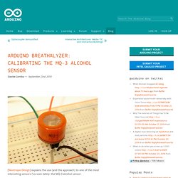
Breathalyzer: Calibrating the MQ-3 Alcohol Sensor. Arduino Breathalyzer: Calibrating the MQ-3 Alcohol Sensor Davide Gomba — September 23rd, 2010 [Nootropic Design] explains the use (and the approach) to one of the most interesting sensors I’ve seen lately: the MQ-3 alcohol sensor: The MQ-3 is an alcohol gas sensor that is available for about $5 from Sparkfun, Seeed Studio, and others.
Medical and Health Related Projects with Arduino. BITalino.pdf. What is " uint8_t" Arduino - How can a let my atmega328 run for a year on batteries? Communication between XBee and Processing - Processing 2.0 Forum. Xbee-api. Arduino Lesson 4. Eight LEDs and a Shift Register. Before I go through the code, let's have a quick look at what the chip is doing, so that we can understand what the code has to do.The chip is of a type called a shift register.
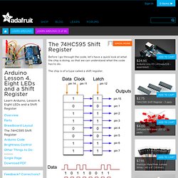
The shift register holds what can be thought of as eight memory locations, each of which can be a 1 or a 0. To set each of these values on or off, we feed in the data using the 'Data' and 'Clock' pins of the chip.The clock pin needs to receive eight pulses, at the time of each pulse, if the data pin is high, then a 1 gets pushed into the shift register, otherwise a 0. When all eight pulses have been received, then enabling the 'Latch' pin copies those eight values to the latch register.
06_02_14_5 Day Summer Semester. Final Lightbar Controller. I've finished the lightbar controller!
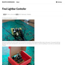
This device analyses the music it picks up via the electret microphone, then flashes the LEDs in time to the music. It's encased in the box SparkFun sent me the microphones in, since the box was just begging to be used as a case for something! I'm sure that was intentionally designed. Connecting Arduino to Processing. Contributors: b_e_n Share Use this URL to share: Share on Twitter Share on Facebook Share on Google+ Introduction So, you’ve blinked some LEDs with Arduino, and maybe you’ve even drawn some pretty pictures with Processing - what’s next? At this point you may be thinking, ‘I wonder if there’s a way to get Arduino and Processing to communicate to each other?’. Using EAGLE: Board Layout. Favorited Favorite 8 Previously on Using EAGLE EAGLE’s board designer is where a good portion of the magic happens.
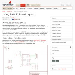
It’s here where the dimensions of the board come together, parts are arranged, and connected by copper traces. In the board editor, the conceptual, idealized schematic you’ve designed becomes a precisely dimensioned and routed PCB. Using EAGLE: Schematic. Favorited Favorite 6 Introduction PCB design in EAGLE is a two-step process.
First you design your schematic, then you lay out a PCB based on that schematic. EAGLE’s board and schematic editors work hand-in-hand. How to Install and Setup EAGLE. Favorited Favorite 9 Introduction Printed circuit boards (PCBs) are the backbone of every electronic gizmo out there.
They’re not flashy like those microprocessors, or abundant like resistors, but they’re essential to making all components in a circuit connect together just right. We LOVE designing PCBs here at SparkFun. It’s a love that we want to spread. This first tutorial goes over how to install the software, and tailor-fit its interface and support files. Ardublock. Easy Driver Examples. Easy Driver Examples Sample code and projects to get your stepper running!
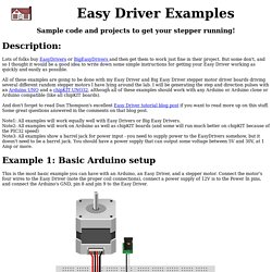
Lots of folks buy EasyDrivers or BigEasyDrivers and then get them to work just fine in their project. But some don't, and so I thought it would be a good idea to write down some simple instructions for getting your Easy Driver working as quickly and easily as possible. All of these examples are going to be done with my Easy Driver and Big Easy Driver stepper motor driver boards driving several different random stepper motors I have lying around the lab.
I will be generating the step and direction pulses with an Arduino UNO and a chipKIT UNO32, although all of these examples should work with any Arduino or Arduino clone or Arduino compatible (like all chipKIT boards). And don't forget to read Dan Thompson's excellent Easy Driver tutorial blog post if you want to read more up on this stuff. Note1: All examples will work equally well with Easy Drivers or Big Easy Drivers. It doesn't get much simpler than that. Bildr. High Sensitivity Arduino Sound Level Detector. Generally we want to sense the environment when something interesting is occurring.
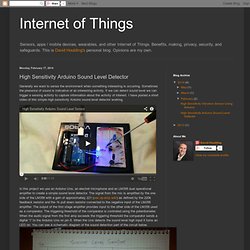
Sometimes the presence of sound is indicative of an interesting activity. If we can detect sound level we can trigger a sensing activity to capture information about the activity of interest. I have posted a short video of this simple high sensitivity Arduino sound level detector working. In this project we use an Arduino Uno, an electret microphone and an LM358 dual operational amplifier to create a simple sound level detector. The signal from the mic is amplified by the one side of the LM358 with a gain of approximately 221 (see op-amp wiki) as defined by the 220k feedback resistor and the 1k pull down resistor connected to the negative input of the LM258 amplifier. Resources. You had such a great time learning to solder your Simon that now you want to take that leap and learn how to program Arduinos.
Luckily the Simon uses the same microcontrollers as Arduinos so you can learn how to add an analog sensors to the Simon and then reprogram it with a FTDI cable. Learn the four basic skills of microcontroller programming: Analog, Digital, Input and Output. Concepts that will be covered include: Stepper Motor Quickstart Guide. Stepper Motor Quickstart Guide Skill Level: Beginner by Joel_E_B | January 03, 2013 | 26 comments Stepping Up to the Challenge There are a handful of motors to choose from, and sometimes it’s unclear as to which one will be best suited for your particular application.
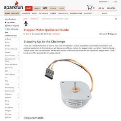
In this tutorial, we will discuss one of these motors, the stepper motor, and when it best to choose a stepper motor over the alternatives. Requirements. SIK Guide v3. Makers the new industrial revolution - chris anderson [qwerty80] Medical and Health Related Projects with Arduino. Www.seas.upenn.edu/~ese111/Fall2012labs/FinalProject-Part1. Introduction to Hardware Hacking with Arduino. Welcome to the Arduino tutorial I wish existed when I started hardware hacking.
LilyPad Arduino Projects. Microcontroller - How to Get Ambient Temp from Arduino Lilypad Temperature Sensor. How to determine whether a computer is running a 32-bit version or 64-bit version of the Windows operating system. This article automatically determines whether a computer is running a 32-bit or 64-bit version of Windows. This article also describes how to manually determine whether a computer is running a 32-bit or 64-bit version of Windows. Generally, a computer's bit count indicates how much data it can process, the speed with which it can process the data, and the maximum memory capacity. In order to optimize the computer's performance, the bit count of the operating system that is installed on the computer should match the bit count of the computer itself. You are currently using a 32-bit operating system. Use the following methods to determine which version of Windows is installed, as appropriate for the operating system that you are running.
Windows 8.
Dlnmh9ip6v2uc.cloudfront.net/datasheets/Dev/AVR/Tiny_Programmer_v11.pdf. Make: Wearable Electronics: Tools and techniques for prototyping interactive wearables (Make : Technology on Your Time): Kate Hartman: 9781449336516: Amazon.com. Full Demonstration of all LilyPad components. The LilyPad Electronic Platform is an electronic platform designed to be easily sewn into fabric using conductive thread, which provides designers freedom from the traditional construction method of soldering.
The LilyPad consists of 3 sensors (temperature, light, and acceleration), a button board, and 4 kinds of output devices: a tri-colored LED, a white LED, a sound board, and a buzzer board. Qatar Foundation International. Profiles in Courage: United For Syria 17-year-old QFI Community Service Grantee, Abdulhassib Al-Jandali, sheds light on the humanitarian crisis in Syria through his campaign United For Syria.
_posts/2011-09-04-servo-photoresistor-arduino.md at master · nrdufour/nemoworld.info. Arduino Candygrabber. DS1307 RTC tutorial. Camera + Turntable + Laser = 360° Scanner.