
Tangent Tutorials. Forum - Full-colour RGB 4x4 button pad (monome-esque) // This is generic code for the 4x4 button pad, with separate routines for every possible event #define DATAOUT 11//MOSI (pin 7 of AD5206)#define DATAIN 12//MISO - not used, but part of builtin SPI#define SPICLOCK 13//sck (pin 8 of AD5206)#define ROWS 4#define COLS 4 #define slavesel(x) ((x<6) ?

0 : 1)const byte rowpin[ROWS] = { 14,15,16,17}; // Using the analog inputs as digital pinsconst byte slaveselect[2] = { 10, 18}; // The pot register numbers for each of the red, green, and blue channelsconst byte red[4] = { 8, 7, 2, 5};const byte green[4] = { 10, 6, 0 , 3};const byte blue[4] = { 11, 9, 4, 1}; // Main data for the drawing routinebyte rGrid[ROWS][COLS] = { 0};byte gGrid[ROWS][COLS] = { 0};byte bGrid[ROWS][COLS] = { 0}; Keyboard Matrix Help. Dave Dribin v1.1 24 Jun, 2000 Attempts to explain how a keyboard matrix works, what "ghosting" and "masking" are, and how to prevent them.

It took me a bit to figure this out, partly due to the fact of no really good explanation of it. So, I'm going to have a crack at it. Basically, I wanted to understand how keyboard matrices work. This article is ©1999-2000 Dave Dribin. The copyright notice above and this permission notice must be preserved complete on all complete or partial copies. Keyboards use a matrix with the rows and columns made up of wires. Figure 1. This keyboard only has 4 keys: A, B, C, and D. The electronic circuit for this matrix looks something (not exactly) like this: In order to detect key presses, the keyboard controller will scan all columns, activating each one by one. To step through this procedure, the controller activates column C1 and checks rows R1 and R2: Figure 3. Neither key A nor C are pressed, so neither row R1 nor R2 is activated.
Figure 4. Figure 5. Pull-up resistor. Pull-up resistors are used in electronic logic circuits to ensure that inputs to logic systems settle at expected logic levels if external devices are disconnected or high-impedance is introduced.

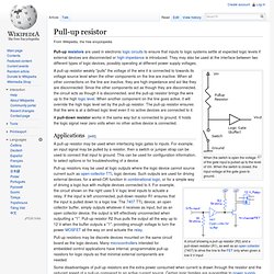
They may also be used at the interface between two different types of logic devices, possibly operating at different power supply voltages. When the switch is open the voltage of the gate input is pulled up to the level of Vin. When the switch is closed, the input voltage at the gate goes to ground. A pull-up resistor weakly "pulls" the voltage of the wire it is connected to towards its voltage source level when the other components on the line are inactive. When all other connections on the line are inactive, they are high-impedance and act like they are disconnected. A pull-down resistor works in the same way but is connected to ground. Applications[edit] A pull-up resistor may be used when interfacing logic gates to inputs. Upward, not northward: My first project: Full-colour RGB monome clone (Trinome?) SPIDigitalPot. Learning Examples | Foundations | Hacking | Links Controlling a Digital Potentiometer Using SPI Examples > SPI LIbrary In this tutorial you will learn how to control the AD5206 digital potentiometer using Serial Peripheral Interface (SPI).

For an explanation of SPI see the SPI EEPROM tutorial. Digital potentiometers are useful when you need to vary the resistance in a circuit electronically rather than by hand. Hardware Required AD5206 Digital Potentiometer Arduino Microcontroller Module 6 Light Emitting Diodes (LEDs) 6 220 ohm resistors Hookup Wire Introduction to the AD5206 Digital Potentiometer Click for for the AD5206's datasheet. The AD5206 is a 6 channel digital potentiometer. Circuit Schematic Code /* Digital Pot Control This example controls an Analog Devices AD5206 digital potentiometer. // inslude the SPI library:#include <SPI.h> // set pin 10 as the slave select for the digital pot: const int slaveSelectPin = 10; Papareil Synth Labs. Spark Fun Electronics.