
Dieselpunk USB Lamp. This Instructable will show you how to take a plain USB LED computer lamp, and turn it into an original Dieselpunk accessory for your Dieselpunk or Steampunk keyboard or laptop.
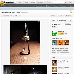
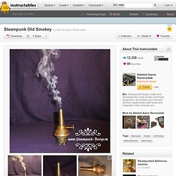
You may be wondering: What is Dieselpunk? Dieselpunk is a lesser known offshoot of the Steampunk phenomenon. As Steampunk harkens back to the Victorian era, or the "Age of Steam," Dieselpunk pays tribute to the era loosely bookmarked by the First and Second World Wars, or the "Machine Age. " For a very thorough analysis of the Steampunk and Dieselpunk movements, peruse some of the back-issues of the fine web periodical, Gatehouse Gazette. For more about Dieselpunk, take a trip to the retro-futurist website Dieselpunks.org. Steampunk Old Smokey. Hi all, this is a very fast and easy weekend project.
Emergency light with steampunk technology. Steampunk Terrarium. Steampunked Heart-Beat-Box. Steampunk spectacles. Pomodoro timer with USSR nixie tubes and japanese measure 'masu' 'Masu' is a japanese wooden cubic box which was used to measure correct volume of rice,soy sauce and so on in japan for 1300 years.
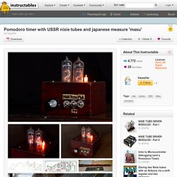
Historically,it was very important because rice was used as tax and salary,as salt did in ancient Greece.First mention about Masu can be found in the statute books written in early AC700,and it was used until 1964. One day i found old Masu at flea market in Tokyo,which was built just after WW2 and used to measure liquid,maybe soy sauce or oil. I decided to build a timer using this Masu and nixie tubes,both abandoned technologies. it was my first touch for PCB CAD(i used EAGLE but finally i could design board schematics. i ordered Olimex( in Bulgaria to build my PCB.They did their job perfectlly. i burned Arduino firmware to ATmega168 as controller. After soldering items,it fits to the inner space of Masu. I will reduce switch from 3 to 2 in next time.but as prototype,i'm totally satisfied. Technology - Steampunk - How to Make Instructables. Most Detailed Steampunk Keyboard Instruction. "The Steampunk Garden" in a bulb. Steampunk-Plasma-Telegraph.
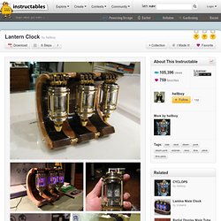
Steampunked nixie-tube-switch. Lantern Clock. Hello All here is my first Instructable, It’s a beautiful Nixie Lantern clock, A little steam punk and a bit Victorian, made up of mostly of found components I tend to communicate better when there is something to show so please look at the images and tags, they sometimes will hold more info than the body of text.
Desktop Power Supply v1.2. I do not have time right now to put an instructable together, however I thought I would post this to get others to come up with better looking desktop power supplies.
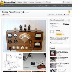
This one has a 1.24 - 10v DC out with amp and voltage meters, a 12v out, 5 v out with amp and voltage meter, and a 110v AC voltage and amp meter! The center tube is a working tube while the left and right tubes are burnout. All 3 tubes have been converted to work on 2 volts (a small light bulb inside the smaller tubes and a light out side in the back of the larger). What I will do over the next few mouths is to post short instructables leading up to the final power supply I will build in January so keep an eye out. The system power (on and off) is controlled by one large relay, this is done so that the 110v AC socket on the right side of the power supply is not routed through the box or the 2 amp switch just a small current now flow from the switch to the relay.
The Simple Tesla Coil. This is a guide on how to build a medium sized Tesla coil.
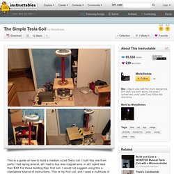
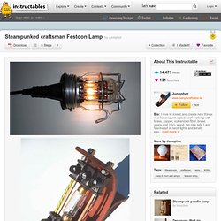
I built this one from parts I had laying around, all I had to buy was magnet wire, in all I spent less than $30! For those building their first coil, I would not suggest using this a standalone source of instructions. This is my first coil, and I used a multitude of sources to make it. Also, I did the boring math part behind it. At first I tried to skip some of the math, and just "wig it" but that didn't work. Steampunked craftsman Festoon Lamp. Hi everybody One year ago I started my first real DIY project, and nearly at he same time I realised that I`m a Steampunker in my thoughts and doings.
Steampunk spectacles #2. Steampunk Geocaching. Steampunk USB Cable. I’ve seen many creative Instructables on DIY steampunk keyboards, mice and other USB peripherals, but many of these don’t include “steampunking” an important part of these devices – the USB cable.
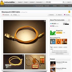
This Instructable will show you how to make a quick, easy and inexpensive steampunk USB cable for your retrofitted, retro-historical steampunk or dieselpunk devices. Note: This Instructable was inspired in part by the beautiful Steampunk Mouse, posted by Miss Betsy. But this Steampunk USB cable doesn't require as many tools, or as much skill as is required to recreate Miss Betsy's steampunk cable. I also borrowed a few ideas from an Instructable on Cloth Covered Banana Cables. Materials: • Bootlace • USB Cable • “F” type quick connect video adaptor • Altoids tin • Glue (Crazy or Gorilla) • Heat shrinkable wire wrap (or brass eyelets) • Gold or bronze metallic paint • Female-to-female "F" type connector (optional)