
The Back Shed: Spud. DingesSenior Member Joined: 04 January 2008Location: Albania Online Status: OfflinePosts: 510 Oztules, I have another PC PSU related question, if you can spare the time.
I'd be very interested in your take on things, especially w.r.t. to the PC PSU option.... I'm toying with the idea of building a micro-TIG welding machine (basically plain TIG, but for delicate work, welding currents 0.1-10A). ATX_power_supply_schematic.pdf (application/pdf Object) Fully Regulated ATX Power Supply - BOGIN, JR. Now, let me begin this article by stating that this *is not* a so-called “conversion” with an LM317 (or any other linear regulator in general) like you might have seen on thousands of other web pages, nor a so-called “lab” supply that was made just by shorting the PS-ON pin.
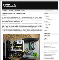
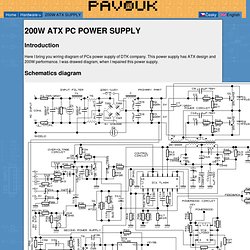
This is a real ATX to regulated supply conversion, which might come in handy for you. The reason why I have chosen to make this article was the increasing number of popularity of my ATX supply hack, which I posted on 4hv.org and simultaneously on Youtube in August 2011. A lot of people started to ask me for a schematic, however I had to respond that there was no universal one. For every different kind of supply the approach is the same, however parts involved might differ a bit. No LM317′s and no huge heatsinks… To change the output voltage of a power supply like this, you need to alter the feedback (PWM) circuit of the driver IC. Step 4: If you are instructed to proceed here, unplug the PSU, fast. 200W ATX PC POWER SUPPLY. Introduction Here I bring you wiring diagram of PCs power supply of DTK company.
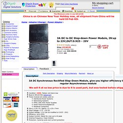
Basic Switching Power Supply Design Tutorial. 3A DC to DC Step-down Power Module, IN:up to 23V,OUT:0.925 - 20V... 3A DC Synchronous Rectified Step-Down Module, give you higher efficiency than regular Asynchronous module We sell it at so low price is due to it is used part, but was tested before shipping Condition: USED, Tested, not brand new Biuld in MP2307DN (datasheet) These modules are widely used on: Distributed Power Systems Networking Systems FPGA, DSP, ASIC Power Supplies Green Electronics/Appliances Notebook Computers Size (L x W x H): Approx. 21 x 20 x 7mm Input Voltage: 4.75 - 23V DC Output Voltage: 3.3V (can be modified to 0.925 - 20V) Efficiency: Up to 95% Output Current: Rated 3A, max up to 4A peak Internal Frequency: Fixed 340KHz Protection: Cycle-by-cycle over current protection The typical application for MP2307 is (not real circuit in KIS-3R33S): As you can see, you just need to change the ratio of: (R1+R2)/R2, the output voltage is(V): (R1+R2)/R2 * 0.925, the output voltage range is 0.925 - 20V. modify the module like follow and get full range of output (0.925 to 20V):
221 - Lab Power Supply Design - Part 1. Untitled. A buck converter or step-down switch mode power supply can also be called a switch mode regulator.
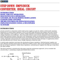
Popularity of a switch mode regulator is due to its fairly high efficiency and compact size and a switch mode regulator is used in place of a linear voltage regulator at relatively high output, because linear voltage regulators are inefficient . Since the power devices used in linear regulators have to dissipate a fairly large amount of power, they have to be adequately cooled, by mounting them on heatsinks and the heat is transferred from the heatsinks to the surrounding air either by natural convection or by forced-air cooling. Heatsinks and provision for cooling makes the regulator bulky and large.
In applications where size and efficiency are critical, linear voltage regulators cannot be used. A switch mode regulator overcomes the drawbacks of linear regulators. The buck converter is introduced in this page using the evolutionary approach. Buck Switching Converter Design Equations. Buck Switching Converter Design Equations The buck converter is a high efficiency step-down DC/DC switching converter.
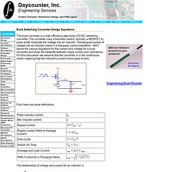
The converter uses a transistor switch, typically a MOSFET, to pulse width modulate the voltage into an inductor. Rectangular pulses of voltage into an inductor result in a triangular current waveform. We'll derive the various equations for the current and voltage for a buck converter and show the tradeoffs between ripple current and inductance. For this discussion we assume that the converter is in the continuous mode, meaning that the inductor's current never goes to zero.
First, here are some definitions: The relationship of voltage and current for an inductor is: ,or For a constant rectangular pulse: From this we can see that the current is a linear ramp, when the voltage is a constant pulse. When the transistor switches on the current is: , or and when the transistor switches off the current is: DC-DC converter. Today, you shall learn a bit about Simple DC-DC converters.
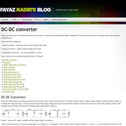
And then proceed towards higher complexity. The complexity rises due to slightly more noise filtering, smoothing,etc There are three categories, 1. Buck Converters – Normally lower output voltage than Input 2. 3.