
Electronics-Projects & Circuits. Solenoid, Door Bell, Electromagnet. Solenoid Make an electromagnet to move a plunger, then use it to make a door bell and a launcher (electric catapult).
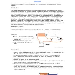
Introduction: You have already made electromagnets with iron cores and examined their magnetic forces. In your experiments you wrapped the insulated wire right over the core; however, you could also wrap the wire on a plastic or paper tube and then insert the nail in the tube. The tube with wire on that will form the coil. Problem and Purpose: Free Online Schematic Drawing Tool. 2n2222 Switch by Holger. Use LEDs as photodiodes. Tests d'appareils photo numériques reflex. Mélanie Lesbats. Iris est un travail que j’ai pu concrétiser pour la manifestation annuelle de la Nuit des Chercheurs. L’association Connaiscience m’a donné les moyens financiers ainsi que le contact d’un scientifique, Henry Reboul chercheur au GRAAL .
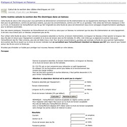
L’association Kawenga m’a proposé un atelier sur Montpellier pour réaliser ce travail. La forme du prisme rappelle celle de sculptures minimales. Le poisson joue le rôle de perturbateur tant visuel que mental. Il suscite maintes interrogations. En guise de source lumineuse, j’utilise un projecteur de diapositives. Part 1 - The Hawking Paradox - BBC Horizon. Relays. Imprimer : Calcul de la section des câbles électriques en 12V. Je ne sais pas si les cosses soudées à l’étain sont interdites en automobile, mais je suis bien certain que les industriels ne le font pas par simple raison économique : en dehors de toute considération de fiabilité cela leur coûterait bien trop cher !
[mode HS on]En restant dans l’industrie automobile il y a un exemple célèbre : comment Citroën s’est fait griller sa célèbre 2CV par la 4L de Renault ? OPEN%20DMX%20adapter_bb. Câble d'alimentation - etanche à 4,85 € (Alimentations éclairage led) BC547B datasheet(3/8 Pages) PHILIPS. General Purpose Transistors NPN Silicon. 2N3904. A 2N3904 in a TO-92 package on a breadboard (lower left) Another 2N3904 The 2N3904 is a common NPN bipolar junction transistor used for general purpose low-power amplifying or switching applications.
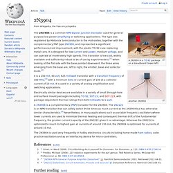
The type was registered by Motorola Semiconductor in the mid-sixties, together with the complementary PNP type 2N3906, and represented a significant performance/cost improvement, with the plastic TO-92 case replacing metal cans. It is designed for low current and power, medium voltage, and can operate at moderately high speeds. This transistor is low cost, widely available and sufficiently robust to be of use by experimenters.[1] When looking at the flat side with the base pointed downward, the three wires emerging from the base are, left to right, the emitter, base and collector leads.[2] Triac ou Transistor en commutation ? MOC / TRIAC + Ardunio. I used a MOC3011 and a Q4015 TRIAC to use my Arduino to blink a few Christmas light strands.
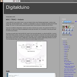
I did this a few months ago, yet never posted it here... The MOC is a optoisolator in a way, as it seperates the arduino from the high voltage 110v circuit. It is also used because the arduino doesn't have the power to directly drive the TRIAC. Systeme de son sphere. Construisez vous même votre système sonore sphérique, et vivez une nouvelle expérience auditive. Unique et insolite, fabriquez vous un objet de décoration fonctionel. 4 Channel 12V Relay Module Shield Expansion Board for Arduino Optical Isolation. 433M superregeneration Wireless transmitting and receiving module theft alarm. Résultats Google Recherche d'images correspondant à. KMtronic LTD: RS485 Serial controlled Eight Channel Relay Board - 12V.
PowerSwitch Tail II. A power cord that switches 120vac power directly from a microcontroller I/O pin (3-12vdc, 3-30ma) "The easiest way to control an AC device with an Arduino, Raspberry Pi, Beaglebone or any other DIY controller.
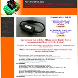
" *** Either unit can be field rewired for normally open (NO) or normally closed (NC) operation. Soldering required. *** No exposed 120vac voltages and no dangerous 120vac wiring required.Plugs into standard 120vac 3-prong household outlets, power strips, and extension cords.Eliminates the exposure of hazardous voltages in DIY projects, classrooms, and on development workbenches.No special 120vac wiring when deploying new products and custom solutions. 5300vrms isolation from the 120vac circuit. Using Relays with Arduino – Turning on the Lights.
Warning!!!

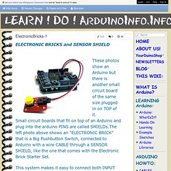
This project deals with AC electricity which is dangerous if you don’t know how to treat it safely. You must treat electricity with caution. There are many books and websites about electrical safety procedures and if you’re not sure how to be safe you should read that information. The most basic advice I can give is always assume any exposed wires are live and touching them will hurt a lot at best and kill at worst. Microcontrollers are good at controlling small devices, but frequently we DIY-ers want to use them to control things that aren’t so micro. The first thing you need is a cheap extension core that you are willing to cut in half. I spliced the relay into the black wire on my power cord. Connecting a Relay to Arduino. ElectronicBricks-1.
Get your brand new Wikispaces Classroom now and do "back to school" in style. guest Join | Help | Sign In.
ArduinoPower. (Power Switching devices for Arduino) Left-Right: A "relay electronic brick", a 4-relay board, an 8-relay board, a 4-Power-FET "brick" Having your Arduino control higher-power devices like lights, motors, pumps, doors, and many more is one of the most interesting and useful applications you may get involved with.

But it can be a little difficult and possibly dangerous when power line voltages are being controlled. There are significant differences in controlling AC power compared to DC. And there are considerations about different kinds of loads and so forth. Connecting a 12V relay to Arduino. Electronic brick -5V Relay module (digital) [ELB115E4M] - $6.50. Controllable Power Outlet. In this tutorial we will discuss a small relay board to control the power to a normal AC outlet using 5VDC control.
All the usual warnings apply: Main voltage (120VAC or 220VAC) can kill you. This project, done incorrectly, could certainly burn down your house. Have your pet spayed or neutered. Shampoo is better. GEG-controler-appareils220V-midi.pdf (Objet application/pdf) Commande Moteur avec Transitor MOSFET. Disconnected / Cosketch. Editing "Unnamed Circuit".