
Serial Streaming. Not very happy with the performance I get from in displaying the images coming from my Arduino Module I decided to build a dedicated application to “see” the image instead. Is part of a bigger project, my “stereoscopic vision” project ^_^ Kind of a long shot, but sounds like a lot of fun. Anyway, I start learning VB and for the past 2 days I tried to code a small application that connects to the serial port, retrieve the data streamed by the camera and display it at high speed (hmm… sort of anyway) in a window. First, I am planning to use 8 bit per pixel, however, not happy with the 256 color per pixel option, looking more for a 4096 colors per pixel instead, so I decided to get pump 12 bits per pixel in only 8 bits… Cool, right? The trick is simple: for each pixel I stream 8 bits, each bit contain 4 bits for green (G) and 4 bits for blue (B) and next one 4 bits for green and 4 bits for red (R) so 2 adjacent pixels share the same B or R information at 12 bits per pixels, voila!
Arduino Based Open Source Camera. OV7670_with_AL422B_test. Hi When i have test with ov7670 camera without AL422 FIFO, The output is something wrong .

The strange is what i have color bar register set to ov7670 camera then the camera's output image is corrupt. The output image is seem like that test pattern color bar mixed with current view in camera. When i have moving camera viewpoint, the ov7670 camera test pattern color bar output image is activated on outside. like this By the way, when i have stuff up ov7670's camera lens, then the ov7670 camera test pattern color bar output image is good. like this I don't understand why this happen ? Here's register setting.. write_i2c(0x12,0x80) ; RESET CAMERA Sleep(200); write_i2c(0xb0,0x84); Arduino – Using a Sharp IR Sensor for Distance Calculation. Well, looks like my sonar sensor (SRF05) is a just a tad inaccurate for precise measurement as I found from my radar screen I made (Arduino Radar Sscreen).

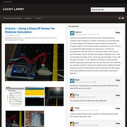
So I’ve got hold of a Sharp GP2Y0A02 series infrared distance sensor. It’ll detect and measure anything within a 20-150cm range and it does this by triangulation from where it emits a beam of IR and from when it receives it – this isn’t too important to understand. The hardest bit of this is actually just getting a rough distance value out of it. If we look at the data sheet you’ll see a graph of Volts to Distance and the greater the voltage the shorter the distance. So to measure distance we’ll need to measure the voltage change as the distance changes. To do this I have to use the analog pins on the Arduino board, now first off because we’re connecting/ reading directly from the sensor we need to convert the digital value that the Arduino’s onboard analog to digital converters will give us. 5v/1024 = 0.0048828125 1/Volts * 65.
LEDs and Multiplexing. 24.gif (GIF Image, 544 × 572 pixels)