
NRF24L01 Transceiver and Arduino. This one’s for techies only!
The NRF24L01 2.4Ghz transceiver. So you have your Arduino (single-chip micro with bootloader) or similar (could be a PIC project really but you’d have to understand and re-hash the libraries) up and running and you need two of them to communicate. How do you do it? One way is the excellent EASYTRANSFER library (just look up ARDUINO EASY TRANSFER) which among other things lets you define 2 wires for serial communication.. the library can let you transfer arbitrary blocks of data back and forth reliably and at speed, but placing that cable can be a pain depending on location and/or the patience of your spouse. If you need wireless communication at low cost, then perhaps the NRF24L01 modules are for you. The problem I found is that there is SO much incorrect or contradictory information out there I decided to write my own blog on the subject.
So, do you need wireless transfer and you’re happy with maybe 20-30ft with no walls or maybe the next room? ITead Intelligent Systems Blog. We make a nRF24L01 wireless library for IFLAT32, then you can plug the nRF24L01 module on the IFLAT32 and use this library to drive wireless module for communication.
The v1.0 version just provide you some basis function which to initial the module , set the power, speed and so on. Functions: void nRF24L01_HW_Init(void) This function is used to initial the hardware setting of the module, it should be used at the beginning of you main code. unsigned char nRF24L01_Config(unsigned char freq,unsigned char power,unsigned char rate) This function is used to configure some setting of the module like frequent, power and speed. Parameters: unsigned char freq: set the frequent , can be 0-120 , means (2400+ freq)M, so you can let the module work in 2.4G to 2.52G unsigned char power: set the power , it should be ‘P0dBm’,’P6dBm’,’P12dBm’ or ‘P18dBm’ unsigned char rate: set the transmit speed, should be ‘R2mbps’, ‘R2mbps’ or ‘R125kbps’ Set the hardware address of TX and RX.
Continue reading. nRF24 Multi-Network – Allowing for 255 addresses. As the nRF24L01 modules are so cheap I bought quite a lot of them and have been thinking about networking them together.
I have the idea of using nRF24 to be able to find out which other nRF24′s are around then then eventually be able to forward traffic for one another if it can’t communicate with a nRF24 that may be too far away but that’s an idea for later on. The nRF24L01 allows for up to 6 receive addresses but I want to make this much higher so the way I decided to do this was through software and it would allow for up to 255 addresses.
It would use all 32 bytes of data that we can send and its format is: From address (byte 0)To address (byte 1) – address 0 means it’s for everyoneForward address (byte 2) – 0 means it’s a normal packet, 1-255 means to forward it to the addressAcknowledgement (byte 3) – 0 means no ack is needed, 1 means ack is needed back, 2 is the ack to send back, 3 is the ack to send back when forward is completeData (byte 4 to 31) Maniacbug/RF24Network. The Revolutionary Arduino Shield. Yaler - a simple, open and scalable relay infrastructure. Turn Your Arduino Into an ISP. There are a few instances in which it is neccesary to program microcontrollers without a bootloader.
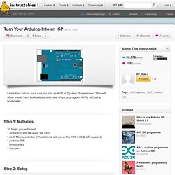
For example, if have run out of storage on a chip you can get an additional 2KB when you program without a bootloader. Another example, the one I will show you how to do, is to program chips that have no serial capabilities and therefore cannot use a bootloader. The ATtiny85 is one of these chips. To program the ATtiny85 using the Arduino ISP you must first add ATtiny85 support to the Arduino environment: * Download attiny45_85.zip * Unzip the folder * Copy the folder to the Arduino IDE's Hardware folder * Reopen the Arduino IDE, you should see the ATtiny85 in the Tools >> Board menu Now connect your Arduino ISP to the ATtiny85 like the diagram below.
EasyTransfer Arduino Library « The Mind of Bill Porter. The purpose of this library is to make it easy for the everyday Arduino user working on projects with multiple Arduinos communicating with each other and sharing data.
I had many people ask me for the code I used in my PS2X library example that sent PS2 Controller values wirelessly to my SAGAR robot. It got to be tiresome answering the questions and I had an idea to write a library to help the inexperienced with micro controller communications. PortManipulation. Reference Language | Libraries | Comparison | Changes Port registers allow for lower-level and faster manipulation of the i/o pins of the microcontroller on an Arduino board.
The chips used on the Arduino board (the ATmega8 and ATmega168) have three ports: B (digital pin 8 to 13) C (analog input pins) D (digital pins 0 to 7) Each port is controlled by three registers, which are also defined variables in the arduino language. The DDR register, determines whether the pin is an INPUT or OUTPUT. DDR and PORT registers may be both written to, and read.