
ESP8266 Full Development Board from saxsena on Tindie. Wifi Arduino85. Designing a Breadboard Adaptor for the $5 ESP8266 Microcontroller. A simple breadboard adaptor for the ESP-01 module.
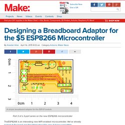
Part 3 of a 3-part series on the new ESP8266 microcontroller TheESP8266 is an interesting new WiFi-enabled microcontroller. We’ve already looked at the board and the talked about the new Arduino-compatible development environment that’s just been released and what it supports. Then we discuss how to install the environment and upload your first sketch onto the ESP-01 breakout board for the ESP8266 SoC.
Now let’s see how to make a breadboard adapter for it. While the ESP-01 is an excellent — and cheap — breakout board for the ESP8266 chip, it’s not a very convenient one to use when you’re breadboarding. Now this isn’t new, there are several other breadboard adaptors for the ESP-01 kicking around, however I decided to design mine so that it was plug and go — once you had your sketch loaded you could take the module away from the computer and just use a 5V supply.
Two ESP-01 modules breadboarded. The Bill of Materials for the adaptor is, Three Channel WiFi Relay / Thermostat Board. The Three Channel WiFi Relay / Thermostat Board is a open software/hardware multi-purpose relay board based on the ESP8266 WiFi SoC.
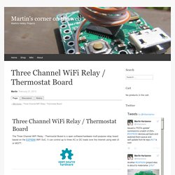
It can control up to three AC or DC loads over the Internet using web UI or MQTT. Highlights Powered by the popular ESP8266 WiFi SoCOn-board power supply unit (optional)Up to three high quality 10A relays for switching AC or DC loads (see DC switching notes)Built-in web server with mobile device friendly UI and HTTP API to control the relaysThermostat function with weekly schedulingManual relay control via the UIMQTT supportNTP for network time and scheduling functionalityWeb server settings, including HTTP port and basic HTTP authentication setupBroadcast relay/sensor data using HTTP GET to services like ThingSpeak or emonCMSIntegration with ThingSpeak for charting/analytics visualizationTemperature sensor support (one of them, not both at the same time) Board schematic & layout Board Schematic Board Layout Design The PCB is 2mm thick with 35 micron foil. Esp8266 XBee carrier board PCB design - 41J Blog. I’ve been putting together a small carrier board to allow a esp8266 board to sit on an XBee connector.
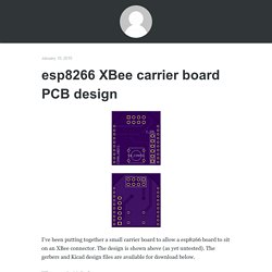
The design is shown above (as yet untested). The gerbers and Kicad design files are available for download below. XBee_esp8266 Gerbers Kicad files (and gerbers) UPDATE: The first rev of these boards came though, I’ll be needing to update the design. UPDATE: Sent out a rev with the header flipped. And the new gerbers: gerbers UPDATE2: The new boards came back, and I’ve now tested them all looks good! Flying, Hiking & Hacking. My as-yet-untested design for a wifi IMU.
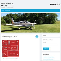
For the past few weeks I’ve been playing with different designs for a Wifi-connected inertial measurement unit (IMU) to use with the open source EFIS I’ve been hacking on for the past year. After breadboarding several designs I decided to take the plunge and create a custom printed circuit board (PCB). Breadboards are great for first-stage prototypes, but they’re too fragile for field testing – especially for an IMU. The original breadboard prototype. ESP8266 Projects: P2 - WIFI Web Power Switch for MAINS - MPSM v.2 DevBoard - ESP8266. WARNING!!
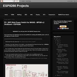
You will play with LIVE MAINS!! Deadly zone!! If you don't have any experience and are not qualified for working with MAINS power I will not ecourage you to play arround! ---------------------------------------------------------------------------------------------------------------------------- Remember the story about the WIFI MAINS Power Switch module? MySensors - What's all the fuss about?
Nano IO Shield with Xbee and NRF24L01 Wireless Interface for Arduino. Dirt Cheap Dirty Boards. Dirt Cheap Dirty Boards. Dirt Cheap Dirty Boards. Dirt Cheap Dirty Boards. Dirt Cheap Dirty Boards. Dirt Cheap Dirty Boards. Dirt Cheap Dirty Boards. Dirt Cheap Dirty Boards. Dirt Cheap Dirty Boards. Dirt Cheap Dirty Boards. OSH Park ~ ESP8266 breakout board. By plogen. 2 layer board of 0.91x0.91 inches (23.16x23.16 mm).
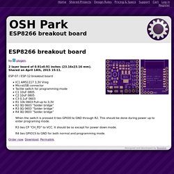
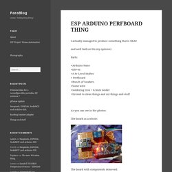
Shared on April 14th, 2015 15:11. ESP-07 / ESP-12 breakout board IC1 AMS1117 3,3V VregMicroUSB connectorTactile switch for programming modeC1 10uF 0805C2 10uF 0805C3 0,1uF 0603R1 10k 0603 Pull-up to 3,3VR2 0Ω 0603 “Solder bridge”R3 0Ω 0603 “Solder bridge”R4 0Ω 0603 “Solder bridge” When the switch is pressed it ties GPIO0 to GND through R2. Order now. 8266.ROCKS. ESP ARDUINO PERFBOARD THING. I actually managed to produce something that is NEAT and well laid out (in my opinion) Parts: • Arduino Nano • ESP-01 • 5-3v Level Shifter • Perfboard • Bunch of headers • Some wire • Soldering Iron + 0.3mm Solder • Dremel to clean things and cut things and stuff As you can see in the photos: The board as a whole:
Connect_to_arduino.png (PNG Image, 1470 × 1119 pixels) - Scaled (69%) Sleek ESP8266 Breadboard Adapter with Pin LABEL. Dirt Cheap Dirty Boards. ESP8266-01 Breakout. This project was designed for the Hackaday Worldwide LA Event and is used to interface a standard USB cable to the ESP8266-01 module.
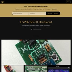
Having spent a fair bit of time using jumper wires and PTH resistors and regulators and such to make a typical 5V0 USB-Serial something ESP/3V3-friendly I decided to build a little board with a few features that simplified the whole workflow. Firstly I added a regulator to provide the necessary 3V3 power when using a 5V0 input. I also added a few pushbuttons as the ESP8266 requires the GPIO0 is pulled low on startup (or low after a RESET) to put it into programming mode. The buttons on both RESET and GPIO0 provide this. I also added an indicator LED and tried to do the whole thing thru-hole so anyone with minimal soldering skills could get in there and solder the board.
Intermittent Technology: ESP8266 WiFi LED dimmer Part 8 of X: Version 2 of the PCB design. With the help of kind internet folks I was able to get a fritzing part for the new voltage converter I wanted to use to try and make a smaller board.
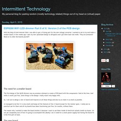
A few weeks ago I sent my new 'panalized' design to dirtypcb's and I got them back last week. They are awesome! Read on to order the boards yourself! Gallery_page.