
Some Guitar Pedals I Have Built. Some Guitar Pedals I Have Built Created and maintained by Paul Marossy, Tonemeister Extraordanaire.
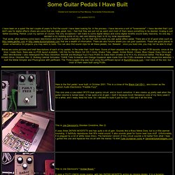
'D'Lay - PT2399 Analog Style Delay Pedal' (GuitarPCB.com) Pedal Kit. Arbiter Fuzz Face. I personally do not think that wiring up PNP transistors (Silicon or Germanium) as negative ground is one of the best ideas.

The PNP transistors are simply not meant to function with a negative ground and osciallation and "motorboating" sounds are common results of wiring a Fuzz Face with PNP transistors as such. Here's some more information from R.G. Keen (GEOFEX): While in theory, the negative ground conversion for FF and other PNP circuits ought to work every time, there are a significant number of times where it causes oscillation, motorboating, etc. Sometimes you can clean this up by putting a big freaking capacitor across the power leads, sometimes you also need a low-impedance 0.1µF ceramic, too, and sometimes you need divine intervention.
So, in my opinion, I would always leave PNP transistor-equipped circuits as positive ground. Small Bear Electronics. Runoffgroove.com. General Guitar Gadgets. New Page 1. A resource for d.i.y. music projects. Das Musikding. [tuto] Treble Booster Germanium 41,55 euros. # Publié le 29 Dec 07, 06:16 pm Salut !
![[tuto] Treble Booster Germanium 41,55 euros](http://cdn.pearltrees.com/s/pic/th/treble-booster-germanium-euros-21054207)
Ce topic vous guidera à travers les étapes de la fabrication d'un Treble Booster DIY avec transistor au germanium NOS (New Old Stock) pour 41,55euros ! C'est un effet assez particulier , ni vraiment un boost neutre , ni vraiment une overdrive boost pour les leads , c'est vraiment un effet hors du commun qui complète idéalement les amplis de conception british type marshall et consorts ... on le retrouve par exemple sur la chanson "bad penny" de rory galagher ( j'ai dû écorcher son nom de famille ) au moment des parties solo. Photos de réalisations d'effets diy et les shemas qui s'y rapportent....
Ecoutez ici le son de + de 500 pédales - forum Effet Guitare. Big Lol GP2 Guitar preamp - Canal SATURE. Ce second canal est certainement la partie du Big Lol GP2 guitar preamp qui se démarque le plus du tout-venat du commerce.
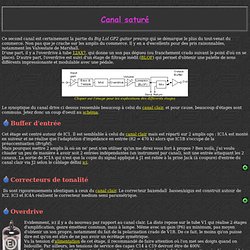
Non pas que je crache sur les amplis du commerce. Il y en a d'excellents pour des pris raisonnables, notamment les Valvestate de Marshall.D'une part, il y a l'overdrive à tube 12AX7, qui donne un son pas dégueu (ou franchement crado suivant le point d'où on se place). Madbeanpedals.Home. Cook Your Own Distortion. Making your own distortion design is easy.
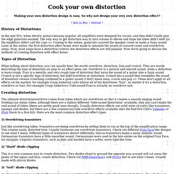
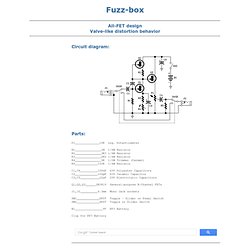
So why not design your very own distortion effect? [ Back to Main | Download ] History of Distortions In the mid 50's, when electric guitars became popular, all amplifiers were designed for vocals, and they didn't really give the edge guitarists wanted. Fuzz-box - RED - Page91. Circuit diagram: Parts: P1______________10K Log.
DIYstompboxes.com. Experimentalists anonymous : Schematics. Circuit Simulator Applet. This is an electronic circuit simulator.
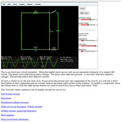
When the applet starts up you will see an animated schematic of a simple LRC circuit. The green color indicates positive voltage. The gray color indicates ground. A red color indicates negative voltage. The moving yellow dots indicate current. To turn a switch on or off, just click on it. The "Circuits" menu contains a lot of sample circuits for you to try. Full Screen version. Directions. Standalone (offline) versions. Design, Analysis & Circuit Theory. Guitar Stompbox & Effects Projects. AMZ Guitar Effects Projects The documents and information on this site may be used solely for personal, informational, non-commercial purposes, and may not be modified or altered in any way.
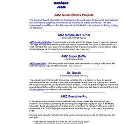
The text, images and sound files on this Site may not be distributed in any manner including posting on web sites. Guitar Effects Pedals, Schematics, Stompboxes & Electronic Projects. AF4K. Comunicamos que o UOL Sites Pessoais foi desativado.

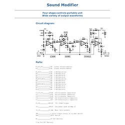
Conheça serviços mais completos e profissionais para a criação do seu site. UOL Conecta Sua página com o endereço que você escolher, por apenas R$9,90/mês (R$6,90/mês para assinantes UOL). Sound Modifier - RED - Page94. Circuit diagram: Parts:
Asmidius. While often used in electronic music, you can oftentimes use a ribbon controller wherever you'd use a potentiometer, with the caveat (at least with this design, which has no sample and hold) that you have to keep pressing down. I've used this design to control display brightnesses and motor speeds, as well as hooking it up to an ADC & microcontroller to send MIDI CC info.
DISCLAIMER: I know very little about electronics, so try this at your own risk! The first thing you'll need is some SVHS video tape... that's SVHS, normal VHS tape, in my experience, will not work. SVHS tapes were used for ADATs, if you remember those. The ribbon controller in this example is made of my old alt.country band's demo tape, and it's Ampex 489, as pictured:
View topic - Interfax - Harmonic Percolator. Re: Interfax - Harmonic Percolator by Kregg » 17 Aug 2009, 23:34 A problem that I had with my Collins HP was the battery holder was too close to the output jack (which for some reason a stereo jack). The battery made contact with the jack and shorted out the circuit. I could have taped over the battery, but, I thought it best to move the battery holder back a half inch.
Now it works! "Political correctness is a doctrine, fostered by a delusional, illogical minority, and rabidly promoted by an unscrupulous mainstream media, which holds forth the proposition that it is entirely possible to pick up a turd by the clean end. " Fun With Tubes. Audio Amplifiers. Modest power audio amplifiers for driving small speakers or other light loads can be constructed in a number of ways. The first choice is usually an integrated circuit designed for the purpose. A typical assortment can be seen on this National Semiconductor page.
Simple Square wave Generator - RED - Page74. Circuit diagram: Parts: R1____________560K 1/4W Resistor R2____________680R 1/4W Resistor R3______________2K2 1/4W Resistor R4____________150K 1/4W Resistor C1_____________12nF 63V Polyester Capacitor C2______________1n2 63V Polyester Capacitor C3____________120pF 63V Polystyrene or ceramic Capacitor C4,C5__________10µF 25V Electrolytic Capacitors Q1,Q2________BC549C 25V 100mA NPN High-gain Low-noise Transistors SW1____________SPST Slider Switch SW2____________1 pole 3 ways Rotary Switch B1_____________1.5V Battery (AA or AAA cell etc.)
Comments: This simple circuit generates a good and stable 1V peak-to-peak square wave at 100Hz, 1KHz and 10KHz using a single 1.5V cell as power supply.