
General Guitar Gadgets - Home. Resistor color code calculator - 3, 4 and 5 band resistors. The calculator above will display the value, the tolerance and performs a simple check to verify if the calculated resistance matches one of the EIA standard values.
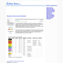
Select the first 3 or 4 bands for 20%, 10% or 5% resistors and all 5 bands for precision (2% or less), 5-band resistors. Hover above the tolerance for min. and max. range values. If you want to find out the color bands for a value, use the tool on the left. Enter the value, select the multiplier (Ω, K or M), the desired precision and hit 'Display resistor' or ENTER. You can also type in resistor values in shorthand notation like 1k5, 4M7 or 100R. Standard EIA Decade Resistor Values: E6 series: (20% tolerance)10, 15, 22, 33, 47, 68 E12 series: (10% tolerance) 10, 12, 15, 18, 22, 27, 33, 39, 47, 56, 68, 82. BrianMayboost.jpg (JPEG Image, 807x576 pixels)
Fuzz Central. I personally do not think that wiring up PNP transistors (Silicon or Germanium) as negative ground is one of the best ideas.
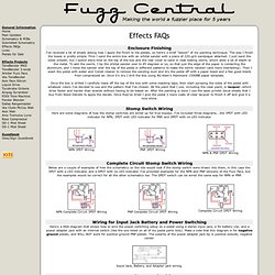
The PNP transistors are simply not meant to function with a negative ground and osciallation and "motorboating" sounds are common results of wiring a Fuzz Face with PNP transistors as such. Here's some more information from R.G. Keen: While in theory, the negative ground conversion for FF and other PNP circuits ought to work every time, there are a significant number of times where it causes oscillation, motorboating, etc. Sometimes you can clean this up by putting a big freaking capacitor across the power leads, sometimes you also need a low-impedance 0.1µF ceramic, too, and sometimes you need divine intervention. So, in my opinion, I would always leave PNP transistor-equipped circuits as positive ground. Homemade PCBs for Effects Pedal Projects.
Jun 22 This article looks at a common alternative method to using press ‘n’ peel transfers, hand drawn layouts, or routed boards.
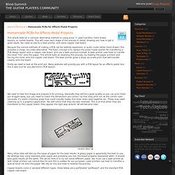
This will cover each stage of the process in detail, showing you how to get a good result. You need access to a laser printer, and some copper clad board. Because the normal methods of making a PCB can be relativly expensive, or quite crude (when hand drawn) this provides a cheap, accurate alternative. The basic concept is to replace the press’n'peel system for transfering a PCB design layout onto a copper clad board, and use a laser printout instead.
Firstly we need to look at the print out. We need to take this image and prepare it for printing. Many other sites will discuss the types of paper for the best results. Copper boards come in serveral different types. Once you have the printed PCB layout on paper, you can cut out a section of copper board. Line up the paper to an edge of the board, and mark out a line to cut out. The finished transfer. Google Image Result for.