
How to debounce a switch. How to de-bounce a switch using CMOS & TTL It has come to my attention that there is a definite lack of understanding on how this simple procedure is achieved.
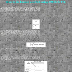
Especially for low numbers of switches in non-microprocessor controlled devices. If the number of buttons you require on your front panel numbers less than 16 then this is how you get a clean button press. You can use CMOS or TTL but the component values change. I'll show the component values for CMOS but it should be noted that the values should also be sweetened to taste.
Figure 1 shows the basic arrangement. However CMOS and TTL don't like smooth transitions. There are a number of parts in both CMOS and TTL. Above is the full debounce circuit using one sixth of a 74C14 package. JTAGTest: Affordable JTAG testing and development solution. » PIC18F2550 USB HID Oscilloscope semifluid.com. This is a project that I’ve been planning on putting together for a long time. After creating an oscilloscope using a PIC12F675, I wanted to create a simple and effective USB oscilloscope using the higher performance PIC18F2550. During the development of this project, I learned quite a bit about USB HID communication, which allows me to quickly and effectively communicate with the desktop computer. Using HID means that this oscilloscope does not require drivers (only the oscilloscope software). Full Circuit The source and firmware for the circuit can be found at the bottom of the page. Analog Input. A logic analyzer using the PC's parallel port.
Last changed: 10/09/2009 16:52:25 Introduction.
A logic analyzer is useful in electronic development and debugging, especially where fast logic circuits are involved with lots of signals whose relations have to be verified or examined. A logic analizer is a like a recorder for digital signals. During a certain (small) period of time, the state of a few digital lines can be recorded to a file. An event can be specified to signal the start of the recording, i.e. line 1 toggeling from 0 to 1. Features This logic analyzer can: Run on Win95 and Win98 and ME using non-interrupted burst acquisition. Run on Win2000 NT XP with interrupted acquisition, using the allowio driver. Simplelogicanalyser - uvasux. Simple Logic Analyser The idea is to build a circuit and computer software that will turn my computer into a logic analyser.
I'd like to be able to inspect logic values within a digital circuit. This circuit is unbelievably easy: it only uses one IC and needs no external power supply. The logic analyser (schematic) is basically a buffer between the user's circuit and the parallel port using a 74hc4050 hex non-inverting buffer.
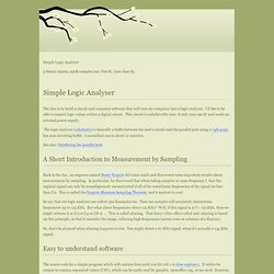
I assembled one in about 10 minutes. See also: Interfacing the parallel port. A Short Introduction to Measurement by Sampling Back in the day, an engineer named Harry Nyquist did some math and discovered some important results about measurement by sampling. So say that our logic analyser can collect 250 Ksamples/sec. So, don't be alarmed when aliasing happens to you. Easy to understand software The source code for a simple program which will capture data until you hit ctrl-c is slow-capture.c.
Faster Sampling Faster Sampling, Smaller Data Files. The Fabulous Logic Analyzer #1. What is a logic analyzer?
A logic analyzer is a device which can monitor the high and low states of several input lines of a digital logic. It is useful for debugging digital circuits such as bus transfers, etc. You can imagine a logic analyzer to be something like a digital oscilloscope. Normally, a logic analyzer is a external device with a own controller that has a own display or is connected to a PC via USB or serial line. The PC or the display then shows the data, e. g. some waveforms. What's special about TFLA-01? This logic analyzer is designed to be cheap, somehing like a logic analyzer for poor men, which means not for industrial use but for hobbyists. There's no real external device which collects the data: The schematic just protects the parallel port and converts RS232 level (+/- 12 V) to 5 V TTL level on two pins configurable with jumpers. This means that the speed depends on your PCs parallel port and on the operating system.
The software has following features: The Fabulous Logic Analzyer #1. Parallel port logic analyzer. Curious Inventor Blog - Intro to Logic Analyzers.