
Vacuum Tube Power Supply Design. Introduction: Tube Power Supply Design It's time for a little confession: I don't always spend as much time on my power supply designs as I should.
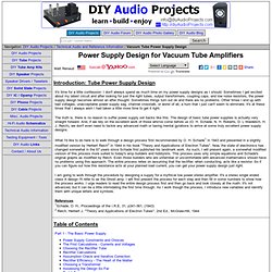
Sometimes I get excited about my latest circuit and after looking for just the right tubes, output transformers, coupling caps, and low noise resistors, the power supply design becomes almost an after thought. Sometimes things turn out ok and there are no problems. Other times I end up with bad voltages, unacceptable power supply sag, channel crosstalk, or worst of all, a hum that I just can't seem to eliminate. It's at these times that I always wish I had taken a little more time to get it right. The truth is, there is no reason to suffer power supply set backs like this. What I'd like to do here is to walk through a design process first recommended by O.
I am going to work through the procedure by designing a supply for a mythical low power stereo amplifier. References1Schade, O. Table of Contents Part 1 - The Basic Power Supply Equation #1. 4S Universal Preamplifier for 12A*7 Tubes. 4S Universal Preamplifier for 12A*7 Tubes Humble Beginnings The basis for this tube preamplifier started out as a post in the Super simple single stage tube preamp thread on the website Forum.
One of the members (see Mark's 4S Universal Valve Preamps) had suggested building a Super Simple Single Stage Preamp ("4S" Preamp for short) and there was much discussion concerning various tubes, gain, noise, etc. and several designs were presented using various dual triode tubes. Then the proverbial gauntlet was thrown down with the phrase "switch from 12AU7 to 12AX7".
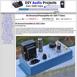
My answer was to design a universal line stage preamplifier that would work well with an entire range of tubes. Photograph 1: 4S Universal Tube Preamplifier - Assembled The Electrical Design - 4S Universal Tube Preamp The tube line level preamplifier design I came up with is a single circuit that can handle the following dual-triode 9-pin tubes with no changes: 12AU7, 12AV7, 12AY7, 12AT7/12AZ7 and 12AX7.
Where: About the Author. The M³ Stereo Headphone Amplifier. M³ Headphone Amplifier. M³ is a 3 channel MOSFET output headphone amplifier inspired by the PPA, SDS Labs, and Hafler DH-200.
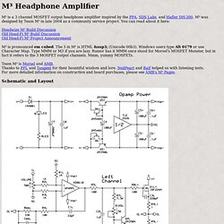
M³ was designed by Team M³ in late 2004 as a community service project. You can read about it here: Headwize M³ Build Discussion Old Head-Fi M³ Build Discussion Old Head-Fi M³ Project Announcement M³ is pronounced em cubed. The 3 in M³ is HTML ³ (Unicode 00b3). Team M³ is Morsel and AMB. Schematic and Layout Features Circuit Description VBE multipliers bias IRFZ24N and IRF9Z34N 18A power MOSFET pairs into Class A operation for low distortion by establishing a constant voltage drop across the gates, which determines the quiescent current. 1µF film capacitors across the VBE multipliers help stabilize the voltage drop and lower impedance at high frequencies. 3 amplifier channels (left, right, and ground) use the same output stage and noninverting opamp topology.
Bass Boost The bass boost circuit is a 6dB/octave low pass shelving filter. Bass Boost Calculator Links Builders. Simplistic Mosfet HV Shunt Regs. JFET Characteristics and Biasing Lab. Switched (Stepped) Attenuator Passive Volume Control. Switched (Stepped) Attenuator Passive Volume Control So I've been wanting to try out one of these ladder type stepped attenuators for a while now.
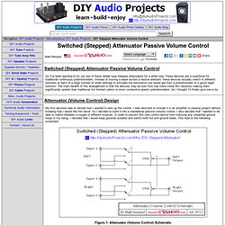
These devices are a substitute for traditional continuous potentiometers. Instead of moving a wiper across a restive element, these devices actually switch in different resistors at each of a large number of shaft settings to simulate the resistance one would get from a potentiometer of a given taper function. The main benefit of this arrangement is that the devices may be built from low noise metal film resistors making them significantly quieter than traditional hot formed carbon or even conductive plastic potentiometers. So I thought I'd finally give one a try. Attenuator (Volume Control) Design My first decision was to decide how I wanted to wire up the control. Figure 1: Attenuator (Volume Control) Schematic Attenuator Selection With the schematic settled I needed to chose an attenuator.
New JFET guitar preamp project. HI Peter, Thank you for your comment, now I see you are a good company >Increasing R4 is a bad idea IMHO.
Normally for guitar amps you see a 1M resistor here. >From what I knough (I'm not ingenier;-) this means that the input will be as noisy as a 1M resistor (called thermal noise??) , Right? >Maybe better to decrease the input impedance to 500K if you can, to get the noise down? No, the input impedance is shunted by pickup resistance, inductance and capacitance, so the input resistor will give rather small contribution in the overall noise. >C1 is too big - I agree. If you design clean channel – what you actually did – don’t change it. >Moving the brightfilter to the input FET is a good idea. Use 10-47nF instead of C2 – it will be bright and shunt it by switch with your 220uF – it will be normal.
>For me the Baxandall-type EQ is the best for guitar - no matter what style I play. Yes, I agree, but the e-guitar is not the source when we can speak about flat frequency response. Yes, it will …