
DFRobotShop Rover V1.5 - Robot à Chenilles Compatible Arduino (Kit XBee) • Version XBee du DFRobotShop Rover• Kit pour robot char d'assaut programmable et polyvalent• Chargeur de batterie LiPo intégré• Carte Arduino complète intégrée (Arduino Uno)• Pont en H double et régulateur de tension intégré (une seule batterie est nécessaire)• Compatible avec différents blindages• 2 modules émetteur-récepteur XBee et interface XBee-USB inclus• Chargeur intégré etCellule de Batterie au Lithium de Polymère SFE - 3,7 V 1000 mAh inclus• Les embases XBee doivent être soudées.

AI on the Web. Artificial Intelligence: A Modern Approach. Bras robotique (avec carte Arduino) - Le forum de la Robotique, www.Robot-Passion.com. Construisez votre robot hexapod avec Arduino - Un podcast vidéo traitant de la robotique. Let's Make Robots!-Mozilla Firefox. Le libre s'envole avec Arduino - Internet Collaboratif. Ordis Solarius Articulum Kapacitusbankus Abampere Quinquaginta OSAKA50. I received a "Animaris Ordis Parvus" leg kit from our friends at Gakken .... AOP :- Just look at those legs .... as a Bonus for sending my SchneeBeast for a Theo Jansen exhibition in Japan.
The original kit was powered by the wind and indeed it drives forwards in the lightest of breezes. ( as proved by rik ) However it was calling out for a bit more power so what i present here is Solar powered version. The basic idea was to split the beest in half and drive both sides independently. With this configuration it can be set up to find and follow the sun.
Driving the motors calls for a "Burst Mode" technique in the form of a Miller Solar Engine. The Miller Solar Engine basically charges up a capacitor bank (6 x 3300uF in my case) from the solar cells. After a predetermined voltage ..... all the power stored in the capacitor bank is transferred into the motor via a drive transistor.. The Gakken magazine in question can be found here.... Otona no Kagaku Magazine (English). Let's Make Robots!-Mozilla Firefox. Triggering a Camera’s Flash with Sound and Light. Update: Check out my latest Camera Axe project for a much more robust device that handles this or my store where I sell the Camera Axe.
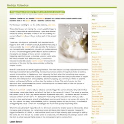
For those just wanting to see the pretty pictures, click here. This article focuses on making the sensors used to trigger a camera’s flash using a microphone or a cheap laser pointer. Since I’ve already described how to do the actual firing of a camera’s flash here I won’t focus on that part of this project today. There are a lot of places on the web that describe how to trigger a flash with an electrical circuit, but I feel that using a microcontroller like Arduino offers big benefits. For instance you can easily add new sensors, or even run multiple sensors at once. Now let’s talk about why we’re triggering the flash. Most SLR and DSLR cameras let you attach a cable to trigger the camera directly. When I’m using this flash trigger I work in a dim room and set my shutter speed to 10 seconds. Laser Sensor Here’s the circuit. Sound Sensor. Let's Make Robots!-Mozilla Firefox.
Hi all, This is it!

As I got a fully (more or less) functional CNC (see here: I can finally start doing what I have intended from the beginning: BUILDING BOTS. This one will scratch my "must build track robot" itch and at the same time I hope I'll be able to use it as a development platform in general, to test various stuff on it. Z-39 aims to be completely build using machined parts. The motors are salvaged from some old CD writer hardware (TIP: there is always good stuff in old hardware ;) ). Arduino. Camera Axe 5 Shield This is the first Camera Axe shield, but it leverages the lessons learned from the previous four generations of Camera Axe hardware.
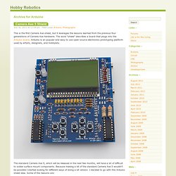
The word “shield” describes a board that plugs into the Arduino board. Arduino is an popular and easy to use open-source electronics prototyping platform used by artists, designers, and hobbyists. The standard Camera Axe 5, which will be released in the next few months, will have a lot of difficult to solder surface mount components. Because making a kit of the standard Camera Axe 5 wouldn’t be possible I started looking for different ways of doing a kit version. There are hundreds of thousands of people who have Arduino boards. Arduino meets processing - PUSHBUTTON. The Arduino meets Processing project intends to make it as easy as possible for anyone to explore the world of physical computing.
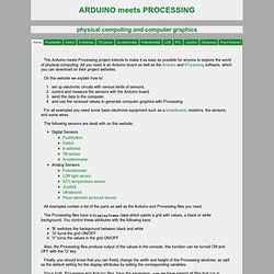
All you need is an Arduino board as well as the Arduino and Processing software, which you can download on their project websites. On this website we explain how to: set up electronic circuits with various kinds of sensors, control and measure the sensors with the Arduino board, send the data to the computer, and use the received values to generate computer graphics with Processing. Sweep. Learning Examples | Foundations | Hacking | Links Examples > Servo Library Sweep Sweeps the shaft of a RC servo motor back and forth across 180 degrees.

This example makes use of the Arduino servo library.