
Untitled. DMG4496SSS-13 Diodes Inc. Richard Thiessen. N-MOSFET half bridge driver - is this a good design? I'm just getting started in electronics.
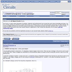
I'm designing a bipolar stepper motor driver. There are two H-bridges in this driver one for each of the motor coils. These H bridges are controlled by a microcontroller based on sensed current to bring the current in each coil to the desired level. I want the H bridges to handle >3 amps at 24 volt. I considered using an integrated h-bridge driver but the low cost drivers seem to be made for <20V supply voltages and 24 volts brings the NCP5359's bootstrap pin to ~34volts, 1 volt under the absolute maximum.
So I decided to design a driver from discrete components. Circuit. Current sensing. This simple circuit will allow your processor to monitor the current being drawn by a motor or any other device. The circuit shown will monitor currents up to 20A which is ideal for the new "Wild Thumper" 6WD chassis. The LM358 is a dual opamp that will work on voltages down to 3V. If you only want to monitor 1 motor then tie the inputs of the second op-amp to ground via 1K resistors so it doesn't generate electrical noise. In the schematic I have not drawn a "H" bridge in detail as this circuit will work with any DC load.
The important thing is that resistors R1 and R2 go between your load and ground. I have shown two 0.1Ω 10W resistors wired in parallel to make a 0.05Ω 20W "shunt" resistor. As current flows through your motor it also flows through your shunt creating a small voltage drop across the shunt that is proportional to the current being drawn. In the circuit shown, with 20A being drawn a voltage of 1V would appear across the shunt (20A x 0.05Ω = 1V). 1307A.pdf (application/pdf-Objekt) Microstep Control - Pseudocode. LED-Konstantstromquelle. [Willkommen] [Kontakt] [Archiv] [Lesezeichen] Allgemeines Leuchtdioden (kurz: LEDs) werden zunehmend auch für Beleuchtungszwecke eingesetzt.
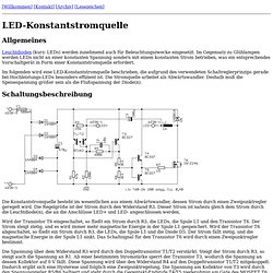
Im Gegensatz zu Glühlampen werden LEDs nicht an einer konstanten Spannung sondern mit einem konstanten Strom betrieben, was ein entsprechendes Vorschaltgerät in Form einer Konstantstromquelle erfordert. Im folgenden wird eine LED-Konstantstromquelle beschrieben, die aufgrund des verwendeten Schaltreglerprinzips gerade bei Hochleistungs-LEDs besonders effizient ist. Modular Circuits. Introduction While developing the µModule H-bridge I’ve learned a lot about H-bridges.
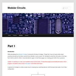
Things that I have not seen written down anywhere but got burnt by them several times (literally in some cases). So I decided to share this information in the hope that it will be useful for others. Usual disclaimers apply so treat these pages as a starting point rather than a panacea. Update: I’m working on a new, much updated version of this series. Xduino-SchematicR1.jpg (JPEG-Grafik, 1024 × 640 Pixel) Current Control Tutorial. Jones on Stepping Motor Current Limiting. Introduction Small stepping motors, such as those used for head positioning on floppy disk drives, are usually driven at a low DC voltage, and the current through the motor windings is usually limited by the internal resistance of the winding.
High torque motors, on the other hand, are frequently built with very low resistance windings; when driven by any reasonable supply voltage, these motors typically require external current limiting circuitry. There is good reason to run a stepping motor at a supply voltage above that needed to push the maximum rated current through the motor windings. Running a motor at higher voltages leads to a faster rise in the current through the windings when they are turned on, and this, in turn, leads to a higher cutoff speed for the motor and higher torques at speeds above the cutoff.
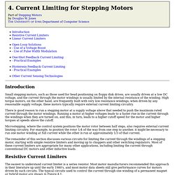
Microstepping, where the control system positions the motor rotor between half steps, also requires external current limiting circuitry. Resistive Current Limiters. Hbridge-reference-ualberta-arvp.pdf (application/pdf-Objekt) 3phduo.pdf (application/pdf-Objekt) 00822a.pdf (application/pdf-Objekt) NTMD5838NLR2G ON Semiconductor. An105.pdf (application/pdf-Objekt) Double PWM controlled H-bridge for interfacing with an Arduino. This is a double H-bridge that can be used with PWM to control the output current.
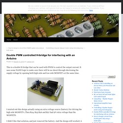
It uses some NAND logic to make sure there will be no shoot-through shortening the supply voltage by opening both high-side and low-side MOSFET’s at the same time. I started out this design actually using an extra voltage source (battery) for driving the high side MOSFET’s. Then R24, R25 R26 and R27 had 9V extra voltage than the MOSFETS.
I didn’t like that solution, and just removed the battery. And the design still worked. My intension for this H-bridge was to use it for an 50V driver for bipolar stepper motor. I did use this with an Arduino, and it worked well. LPC1114 Code Base (Open Source GCC library for the LPC1100) LPC1114 Code Base An open source GCC-based software library for the Cortex-M3 based LPC1100 family The LPC1114 Code Base is a complete open-source (BSD license) software library for NXP's Cortex-M0 based LPC1100 family, with support for all the main internal peripherals, and drivers for common hardware like SPI-based EEPROM, and an I2C temperature sensor (LM75B).

The code base includes complete C startup code and an easy to understand make file and linker script for building from the command-prompt on any OS (Yagarto 4.5.0 was used for builds), as well as project files for the open-source CodeLite C/C++ IDE and the commercial GCC-based Crossworks for ARM (useful for HW debugging). Latest Release A final release has not yet been made yet for the LPC1114 Code Base, and we hope to publish an initial release in the next month or two. DT92-4_High_Side_Driver_with_Charge_Pump__IR.pdf (application/pdf-Objekt) ZXCT1009.pdf (application/pdf-Objekt) Differential Amplifier (Voltage Subtractor) Differential Amplifier Thus far we have used only one of the operational amplifiers inputs to connect to the amplifier, using either the “inverting” or the “non-inverting” input terminal to amplify a single input signal with the other input being connected to ground.
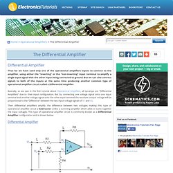
But we can also connect signals to both of the inputs at the same time producing another common type of operational amplifier circuit called a Differential Amplifier. Basically, as we saw in the first tutorial about Operational Amplifiers, all op-amps are “Differential Amplifiers” due to their input configuration. But by connecting one voltage signal onto one input terminal and another voltage signal onto the other input terminal the resultant output voltage will be proportional to the “Difference” between the two input voltage signals of V1 and V2.
Differential Amplifier By connecting each input in turn to 0v ground we can use superposition to solve for the output voltage Vout. Differential Amplifier Equation Price Disclaimer. MT-068.pdf (application/pdf-Objekt) Dn407f.pdf (application/pdf-Objekt) AN10661.pdf (application/pdf-Objekt) Den passenden MOSFET-Treiber finden. Leistungsschalter 16.04.2009 | Autor / Redakteur: Cliff Ellison* / Kristin Rinortner Wie gut der MOSFET-Treiber an den MOSFET der jeweiligen Applikation angepasst ist, hängt neben der Verlustleistung maßgeblich vom Treiberspitzenstrom und den damit verbundenen Ein- und Ausschaltzeiten ab.

Der Beitrag zeigt unterschiedliche Möglichkeiten auf, wie sich der optimale MOSFET-Treiber auswählen lässt. MOSFET n-Kanal Logiclevel. An-978.pdf (application/pdf-Objekt) Mosfet.pdf (application/pdf-Objekt) The Transistor Amplifier. A transistor can be used to amplify the characteristics of a zener.
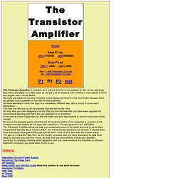
You can also say the transistor is a BUFFER or EMITTER-FOLLOWER. It is another example of the transistor as an AMPLIFIER - a DC AMPLIFIER - indicating it amplifies the "steady-state" conditions provided by a zener diode. We will start with the simple Zener Regulator circuit, then add the transistor amplifier. After that, we will remove the zener and add another transistor to improve the smoothness of the output waveform. A simple zener regulator circuit is very wasteful however it is the basis for creating a stable output voltage from a voltage that may be rising and falling a considerable amount. A Zener Regulator Circuit. N-kanal mosfet treiber diskret mit npn und pnp.
Trimborn's Erfinder-Homepage: Neues Kaskadenprinzip.
AN-7500.pdf (application/pdf-Objekt) Application notes and circuits for Variable Speed Brushless Dc Motor Pre-drivers. Bipolar Tutorial. Microstepping motor controller. Bipolar Tutorial.