
Microcontrollers. Assembler Maths. Op-Amps. 555 Timer Tutorials. LED Lights & Accessories - SUPER BRIGHT LEDS. Bipolar junction transistors as switches : Worksheet. Question 1: Solid-state switching circuits usually keep their constituent transistors in one of two modes: cutoff or saturation.
Explain what each of these terms means. "Cutoff" refers to that condition where a transistor is not conducting any collector current (it is fully off). Bipolar Junction Transistors. Capacitance. Capacitor Voltage Change. This curve fitted equation can then be used in LTSpice to model the Y5U capacitor, with its capacitance versus voltage relationship.
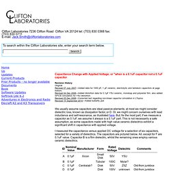
To model a non-linear capacitance in LTSpice, it's necessary to write an equation relating charge (in Coulombs) versus bias voltage. This mathmatical relationship is written into the value of the capacitor (instead of so many uF or pF) as Q=f(x) where X is the pre-defined variable in LTspice representing the instantaneous voltage across the capacitor. More generally, the charge Q stored in a capacitor is: C(V) is the relationship between capacitance and applied voltage, in this case, as determined by our 7th order polynomial fitted to the measured C versus V data: