
Suivre sa consommation d’eau : domotisation d’un compteur d’eau à l’aide d’un arduino. Bonne année à tous (mieux vaut tard que jamais :).

Pour commencer cette année, un petit article sur le relevé automatique de la consommation d’eau. Le montage utilise un compteur d’eau banal du commerce (sans capteur donc) et ne nécessite pas son démontage. Relever sa consommation d’eau : les différentes solutions Pour faire du relevé de compteurs d’eau, il n’y a pas 36 solutions. Il faut que le compteur soit équipé d’un capteur. Les solutions commerciales, « plug&play », fiables … et pas trop bon marché Il existe des compteurs avec une sortie pour un capteur à impulsion?
On le trouve chez planète domotique par exemple : Coté prix c’est mieux mais on va faire mieux La solution du pauvre, play&plug ;), aussi fiables et pas chères ! Comme d’habitude je suis parti sur une solution la moins chère possible et sans sacrifier la fiabilité. AVR Tutorial - AVRDUDE. OK now you have a target board and a programmer next you will use the software you installed in step 2 to talk to the chip.
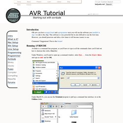
This software is very powerful but its also difficult to use the first time. However, you should persevere and after a few times it will become (easier) to use. Comments? Suggestions? Post to the forum! Avrdude is a command line program, so you'll have to type in all the commands (later you'll find out how to shortcut this with a Makefile) Under Windows, you'll need to open up a command window, select Run... from the Start Menu and type in cmd and hit OK.
Under MacOS X, you can use the Terminal program to pull up a command line interface, its in the Utilities folder. RFLink Wiring Details ⋅ Easy Home Automation. RFLink Wiring Details 01 July 2015 Using a seperate RF receiver and RF transmitter: Prefferred are Aurel RF receivers.
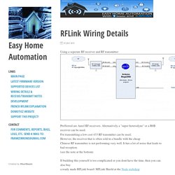
Alternatively a "super heterodyne" or a R6B receiver can be used. For transmitting a low cost 433 RF transmitter can be used. If building this yourself is too complicated or you dont have the time, then you can also buy a ready made RFLink board / RFLink Shield at the Nodo webshop Receivers and Transmitters: Various receivers/transmitters/transceivers have been tested.
Connecter des dispositifs sans fil à votre Arduino ou Raspberry Pi, Partie 1: Réception en 433Mhz / HackSpark, l'électronique facile ! Cette entrée a été publiée le 20 décembre 2012 par Jonathan de HackSpark.
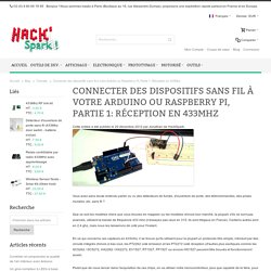
Vous avez sans doute entendu parler ou vu des détecteurs de fumée, d'ouverture de porte, des télécommandes, des prises murales, etc. sans fil ? Que ce soit les modèles chers que vous trouvez en magasin ou les modèles chinois bon marché, la plupart, s'ils ne sont pas avancés, utilisent la bande de fréquence 433 mhz (n'essayez pas ceux en 315, ils sont illégaux en France). Certains autres sont en 2.4 ghz, mais nous les laisserons de coté pour l'instant. En ce qui concerne ces capteurs en 433mhz, il se trouve qu'ils utilisent pour la plupart un protocole très simple, introduit par des circuits intégrés chinois à bas cout, les PT2262 coté émission et les PT2272 coté réception (d'autres plus exotiques comme les SC5262 / SC5272, HX2262 / HX2272, EV1527, RT1527, FP1527 ou encore HS1527 peuvent être trouvés et fonctionneront aussi).
Secret Arduino Voltmeter – Measure Battery Voltage. A little known feature of Arduinos and many other AVR chips is the ability to measure the internal 1.1 volt reference.
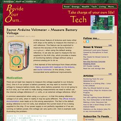
This feature can be exploited to improve the accuracy of the Arduino function – analogRead() when using the default analog reference. It can also be used to measure the Vcc supplied to the AVR chip, which provides a means of monitoring battery voltage without using a precious analog pin to do so. I first learned of this technique from these articles – Making accurate ADC readings on the Arduino, and Secret Voltmeter. In this article, I have incorporated some additional improvements. Motivation There are at least two reasons to measure the voltage supplied to our Arduino (Vcc). A common assumption when using analogRead() is that the analog reference voltage is 5.0 volts, when in reality it may be quite different.
Double Vcc = 5.0; // not necessarily true int value = analogRead(0); double volt = (value / 1023.0) * Vcc; // only correct if Vcc = 5.0 volts How-To Usage. Sans titre. Do you have an Arduino project configured to periodically gather some sensory information and you are noticing it draining power quickly while waiting for the next interval? Do you want to get the maximum operating period on those small batteries? Then it is time to consider implementing a WatchDog Timer (WDT) so conserve power when your device can power down while not in use. So, what is a watchdog timer? A watchdog timer (WDT); sometimes called a computer operating properly or COP timer, or simply a watchdog – is an electronic timer that is used to detect and recover from computer malfunctions.en.wikipedia.org/wiki/Watchdog_timer While typically used to detect when a computer system crashes or becomes unresponsive – it can also be used to wake up a device if it has been on purpose put into a power down state; something that becomes applicable to saving power and reducing power consumption.
#include "LowPower.h" void setup() { // No setup is required for this library }