
UML en français. Tutoriels UML - Club des décideurs et professionnels en Informat. UML Class Diagrams - Unified Modeling Language UML - SmartDraw T. Class diagrams are the backbone of almost every object-oriented method including UML. They describe the static structure of a system. Basic Class Diagram Symbols and Notations Classes represent an abstraction of entities with common characteristics. Associations represent the relationships between classes. Illustrate classes with rectangles divided into compartments. Active Class Active classes initiate and control the flow of activity, while passive classes store data and serve other classes. Visibility Use visibility markers to signify who can access the information contained within a class. Associations. (ootips) Association, Aggregation and Composition. StarUML - The Open Source UML/MDA Platform. WebSequenceDiagrams.com - Create sequence diagrams in seconds.
PlantUML - Wikipedia. PlantUML is an open-source tool allowing users to create UML diagrams from a plain text language.
The language of PlantUML is an example of a Application Specific Language.[3] It uses Graphviz software to lay out its diagrams. It has been used to allow blind students to work with UML.[4][5] PlantUML also helps blind software engineers to design and read UML diagrams. Applications that use PlantUML[edit] PlantUML.com is a web server that generates diagrams in the cloud.
There are also various extensions or add-ons that incorporate PlantUML. Text format to communicate UML at source code level[edit] PlantUML uses well-formed and human-readable code to render the diagrams. There are other text formats for UML modelling but PlantUML supports many diagram types and does not need an explicit layouting, though it is possible to tweak the diagrams if necessary. Example[edit] The source code for the class diagram shown on the right is as follows: See also[edit] References[edit] Sequence Diagram syntax and features. Basic examples The sequence -> is used to draw a message between two participants.
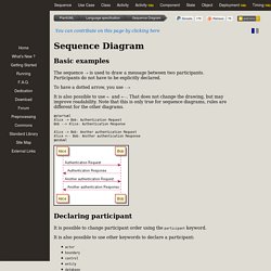
Participants do not have to be explicitly declared. To have a dotted arrow, you use --> It is also possible to use <- and <--. That does not change the drawing, but may improve readability. @startuml Alice -> Bob: Authentication Request Bob --> Alice: Authentication Response Alice -> Bob: Another authentication Request Alice <-- Bob: Another authentication Response @enduml Declaring participant It is possible to change participant order using the participant keyword. It is also possible to use other keywords to declare a participant: actorboundarycontrolentitydatabase @startuml actor Foo1 boundary Foo2 control Foo3 entity Foo4 database Foo5 collections Foo6 Foo1 -> Foo2 : To boundary Foo1 -> Foo3 : To control Foo1 -> Foo4 : To entity Foo1 -> Foo5 : To database Foo1 -> Foo6 : To collections @enduml You can rename a participant using the as keyword.
You can also change the background color of actor or participant. PlantUML, un nouvel outil de génération UML. PlantUML est un outil Java permettant d'écrire très rapidement des diagrammes UML en utilisant un langage texte simple et intuitif.
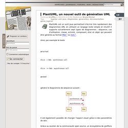
Il supporte actuellement sept types de diagrammes : séquence, cas d'utilisation, classe, activité, composant, état et objet qui peuvent être générés au format PNG ou SVG. Untitled. Untitled. Untitled. UML sequence diagrams overview of graphical notation - lifeline, message, execution specification, interaction use, etc. Sequence diagram is the most common kind of interaction diagram, which focuses on the message interchange between a number of lifelines.
Sequence diagram describes an interaction by focusing on the sequence of messages that are exchanged, along with their corresponding occurrence specifications on the lifelines. The following nodes and edges are typically drawn in a UML sequence diagram: lifeline, execution specification, message, combined fragment, interaction use, state invariant, continuation, destruction occurrence. Major elements of the sequence diagram are shown on the picture below. Sequence diagram - Wikipedia.
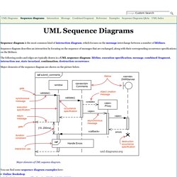
Sequence diagram of e-mail message sequence A sequence diagram is an interaction diagram that shows how objects operate with one another and in what order.
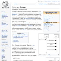
It is a construct of a message sequence chart. UML Cours 5 : Diagramme de séquences. Les diagrammes de cas d’utilisation modélisent à QUOI sert le système, en organisant les interactions possibles avec les acteurs.Les diagrammes de classes permettent de spécifier la structure et les liens entre les objets dont le système est composé : ils spécifie QUI sera à l’oeuvre dans le système pour réaliser les fonctionnalités décrites par les diagrammes de cas d’utilisation.Les diagrammes de séquences permettent de décrire COMMENT les éléments du système interagissent entre eux et avec les acteurs :Les objets au coeur d’un système interagissent en s’échangent des messages.Les acteurs interagissent avec le système au moyen d’IHM (Interfaces Homme-Machine).
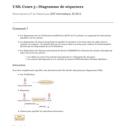
Interaction Pour être complètement spécifiée, une interaction doit être décrite dans plusieurs diagrammes UML : Cas d’utilisation Séquences. UML sequence diagrams overview of graphical notation - lifeline, message, execution specification, interaction use, etc. Nouveautés UML 2.0 : Diagramme de séquence.
Avant de présenter les nouveaux concepts du diagramme de séquence, je vous propose quelques rappels.
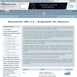
Diagramme de séquence : Un diagramme de classe permet de décrire les interactions entre différentes entités et/ou acteurs : par exemple des objets dans un modèle d'un logiciel, des sous-systèmes dans un modèle d'un système complet. Le temps est représenté comme s'écoulant du haut vers le bas le long des "lignes de vie" (lifeline) des entités. Des flèches représentent les messages qui transitent d'une entité vers l'autre. UML basics: The sequence diagram. UML basics Donald BellPublished on February 16, 2004 It's February, and by now you've probably read about, or heard people talk about, making the change to UML 2.0--the new specification for UML that contains a number of improvements.
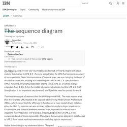
Given the importance of the new spec, we are changing the basis of this article series, too, shifting our attention from OMG's UML 1.4 Specification to OMG's Adopted 2.0 Draft Specification of UML (a.k.a. UML 2). I hate to change emphasis from 1.4 to 2.0 in the middle of a series of articles, but the UML 2.0 Draft Specification is an important step forward, and I feel the need to spread the word. There were a couple of reasons that the OMG improved UML.
Build your next app with IBM Cloud Lite. UML Cours 5 : Diagramme de séquences. Untitled. PlantUML. PlantUML is a component that allows to quickly write.
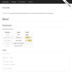
This is cheat sheet of PlantUML to use frequently. Common Notes and Comments. Code title Title ( ) note left : Note [ ] note right : Note ' single-line comment /' block comment '/ Draw.