
App note: Performance enhancement of three terminal voltage regulators. Three terminal voltage regulators like the lm317 are common and easy to use, for most applications only two additional resistors are needed to get a stable power supply.
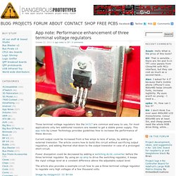
This app note by Linear Technology provides guidelines how to increase the performance of these devices. Current output could be increased from a few amps to tens of amps, by adding an external transistor. The article covers how to build this circuit without sacrificing output regulation, and adding thermal shut-down to the output transistor in case of a prolonged short circuit.
Power dissipation could be decreased by adding a switching dc/dc converter before the three terminal regulator. By using an op amp to drive the switching regulator, it keeps the input voltage level at a constant difference above the adjustable output level. The article also provides a example circuit how to use a three terminal voltage regulator to regulate very high voltages of a few thousand volts. Image by Gelpgim22: CC BY-SA. Cds.linear.com/docs/Application Note/an25fa.pdf. Power Up with Knowledge. Partlist Wednesday: Voltage regulators. Every Wednesday we highlight a component from the updated partlist.
This week: regulators. This week’s part: voltage regulators. We try to use the cheap 150mA voltage regulators in SOT-23 package whenever possible. These are cheap (from 25 cents in 1s) and super resilient to shorts, over temperature, and over load. 150mA is enough for the vast majority of our projects, if we need more power we bump it up to a 800mA SOT-223. For lots of power (1A+), and/or high input voltages, we reach for the DPAK or D2PAK regulators. Unfortunately there’s no standard part number for most regulators. The post interface is giving us problems since the theme update, this week’s partlist post will be cut a bit short.
Package guidelines: SOT-23-5 (SOT-25): 2.9 mm × 1.3/1.75 mm × 1.3 mm body – five terminals SOT-223: 6.7 mm × 3.7 mm × 1.8 mm body – four terminals, one of which is a large heat-transfer pad DPAK (TO-252): discrete packaging. Transistor regulator circuit can adjustable output voltage. See Other projects in : Power supply And: 2N3904, 2SC458, DC variable supply Posted by admin - July 23, 2011 at 6:52 pm This circuit is maintain a constant voltage, the output voltage is adjustable.Serves to reduce the input voltage, and keep the voltage constant.
The Q1 2N3904 is the amplifier model. common-emitter. This causes the voltage across the collector’s pin with the ground.Is equal to the voltage between the legs to the ground base of Q1. The volt base-emitter (0.6 V), the zener diode volt (6.2 V), then adjust the voltage VR1. This circuit has a temperature coefficient is very little, almost zero. The Q2 to drive the output up. Www.nteinc.com/specs/900to999/pdf/nte956.pdf. Constant current source with LM317. Power Supply. Working With High Voltage AC Power *Unless you are familiar with the safety precautions needed and the electrical regulations that are in force in your area, do not work on the high voltage AC portions of power supplies.
Have a qualified technician help you or have them build this portion of the circuit for you. Always include a Ground Fault Circuit Interrupter in your household wiring or as part of an extension cord to supply AC power to home built circuits and your whole layout for that matter. Ground Fault Circuit Interrupter Also, it is far less expensive, safer and easier to buy a new or used, regulated and efficient power supply that is UL or CSA approved than making one yourself using an old iron cored transformer.
In the end, you will be safer, and your insurance agent will be happier, if you use an approved power supply. Using Old Throttle Power Packs As Power Supplies For Electronics Even the more expensive DC power packs should not be used to power electronic circuitry. PSBench.GIF (768×392) 221 - Lab Power Supply Design - Part 1. 222 - Lab Power Supply Design - Part 2.