
BackEMF. Modular Circuits. Introduction While developing the µModule H-bridge I’ve learned a lot about H-bridges.
Things that I have not seen written down anywhere but got burnt by them several times (literally in some cases). So I decided to share this information in the hope that it will be useful for others. Usual disclaimers apply so treat these pages as a starting point rather than a panacea. Update: I’m working on a new, much updated version of this series. In general an H-bridge is a rather simple circuit, containing four switching element, with the load at the center, in an H-like configuration: The switching elements (Q1..Q4) are usually bi-polar or FET transistors, in some high-voltage applications IGBTs.
In general all four switching elements can be turned on and off independently, though there are some obvious restrictions. Basic operation Component selection. Diode_applications. GOduino II = Arduino + L293D Variable Speed Motor Controller. The GOduino II is a self-contained programmable controller for wheel-based robots.
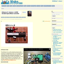
It's an Arduino Uno clone plus an L293D motor driver for under $20. It controls both motor direction and speed.The prototype predecessor to this is the GOduino, a basic version of this controller on a breadboard. I will maintain updates to this guide both here and on my blog I have designed a few basic robots using the Arduino Uno and motor shields. Both are great for prototyping. Also in countries like Jordan where the average monthly income is about $300 and an outrageously high tariff code that's hostile to technology, it becomes a necessity for students and makers to seek locally assembled low cost, repairable alternatives to imported electronic circuits.
The GOduino II works for 2 motors only, and leaves plenty of Arduino pins available for sensors. This may not be state of the art stuff but it does the job for me and my protospace members. This project is based on the works of so many good folks. Closed loop speed control of DC motor using back emf sening - hobbydebraj. Working on motor control had always been my passion.
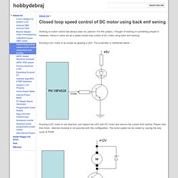
For this project, I thought of working on something simpler in hardware. Hence it came out as a speed closed loop control of DC motor using back emf sensing. Running a DC motor is as simple as glowing a LED. The schematic is mentioned below: - Running a DC motor in one direction, just replace the LED with DC motor and remove the current limit resistor. But a common problem with this schematic for DC motor control is that if the motor is loaded (mechanical load), the motor speed reduces. For sensing the motor speed and feeding it back to controller, usually, some transducer (sensor) is used such as: - 1. These sensors are great, but all of them cost money. A DC motor when driven by external means, will generate a voltage. Some advantage of using this control scheme: - 1. Where this scheme cannot be used: - 00893a. DavesBEMFmotorArticle. PID controller using Back EMF as the Control Feedback Usually when implementing a PID motor controller you would need an external opto-mechanical encoder or magnetic sensor to determine the position of the motor.
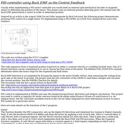
This project uses no external position detecting parts, but instead uses the back EMF generated by a motor in order to determine position. Inspired by an article in the August 2004 Circuit Cellar magazine by Rich LeGrand, the following project demonstrates positional PID control of a single motor. It's implemented using a PIC16F88, an L293D four channel driver and a few resistors. Click drawing for larger image The code was written using the CCS C compiler. Back EMF detection is accomplished by floating the inputs to the motor briefly (500us), then measuring the voltage from each side or the motor to ground.
PID control is implemented in PIDfb() and uses the standard proportional, derivative and integral calculations. Here are some details on the functions of the C program: Robidouille. Software motor control and back EMF as position feedback. Back-EMF Motion Feedback. Electromotive force (EMF) refers to the voltage generated by a spinning motor.
Measuring this voltage in order to determine the rotational speed of a motor is commonly called Back-EMF since the voltage tends to "push-back" against the circuit driving current into a motor's windings. This speed indication may be used in motion control algorithms to modulate the velocity or to compute the angular distance the motor has traveled over time. The details of Back-EMF based motion control feedback are presented below. Typically a motor takes power in the form of voltage and current. This power is converted over time into mechanical energy in the form of rotation. Back EMF « Robidouille. As promised, here are some more details on how I implemented back-emf to control the wheel’s rotational speed.
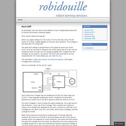
First, what is back-emf exactly? Low-Cost Bidirectional Brushed DC Motor Control Using the PIC16F684.