
Edward d-tech website - music. Yamaha Chips This is an attempt to create the most extensive Yamaha synth chip list ever.
Includes hard/impossibe to find pinouts, too. Information, that I add here, is mostly checked/confirmed/found out by myself, unless otherwise noted. Currently under construction. I am going to fill up the cells, add pinouts, missing entries and lists gradually, whenever I will find some spare time for doing it. Распайка, распиновка, データシート By the way, I do not sell these chips. This reference table also allows to quite precisely assess the character and quality of the sound for a particular keyboard, by knowing the sound of other similar ones.
YM series YMF, YMM, YMW series YA series YSS/YSP/YSD series Custom Yamaha chips from miscellaneous chip fabs iG custom ASICs. Art's Theremin Page: Four Phase Clock Generator. Four Phase Clock Generator Here is an extremely useful circuit that may be applied as the timing core for any sequential digital process, using a single dual-flip-flop package, CMOS type CD4013BE.
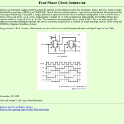
One of the four outputs (phase 1) provides a squarewave at one-quarter the clock input frequency. The phase 2 output provides a squarewave one clock cycle later, and phases 3 and 4 follow with a delay of two and three clock cycles, respectively. A supply of +5 volts is indicated, although the CD4013BE device may operate within a range of +3 to +15 volts. The maximum recommended clock rate is 3.5MHz for a +5 volt supply. My gratitude to Rick Hansen, who introduced me to this circuit and the essential tenets of digital logic in the 1980s.
November 30, 2012 Text and image ©2012 by Arthur Harrison Back to the Circuit Library Index Back to the Opening Page of Art's Theremin Page. Art's Theremin Page: Symmetrical Digital Dividers. Symmetrical Digital Dividers These digital divider circuits permit the division of a frequency by odd integers (three, five and seven illustrated) while maintaining an output with a nearly-perfect 50% duty cycle square wave.
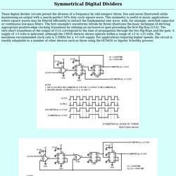
This symmetry is useful in music applications where square waves may be filtered efficiently to extract the fundamental sine wave, with, for example, switched capacitor or continuous low-pass filters. The first example's waveforms (divide by three) illustrates the basic technique of deriving appropriate positive-edge clocking transitions by utilizing an exclusive-or gate preceding the first flip-flop (U1A). The very-short transitions at the output of U1A correspond to the time of propagation through the two flip-flops and the gate. A supply of +5 volts is indicated, although the CMOS devices shown operate within a range of +3 to +15 volts. December 11, 2012 Text and image ©2012 by Arthur Harrison Source documents dated May 1, 1997.
Art's Theremin Page: Twin-T Audio Sine Wave Oscillator. Twin-T Audio Sine Wave Oscillator The circuit illustrated produces a clean sine wave signal ideal for audio testing, or wherever a good-quality sine voltage source is required.
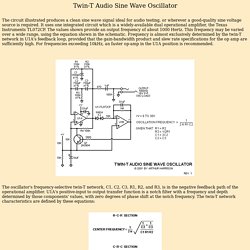
It uses one integrated circuit which is a widely-available dual operational amplifier, the Texas Instruments TL072CP. The values shown provide an output frequency of about 1000 Hertz. This frequency may be varied over a wide range, using the equation shown in the schematic. Frequency is almost exclusively determined by the twin-T network in U1A's feedback loop, provided that the gain-bandwidth product and slew rate specifications for the op amp are sufficiently high.
The oscillator's frequency-selective twin-T network, C1, C2, C3, R1, R2, and R3, is in the negative feedback path of the operational amplifier. The positive feedback required for oscillation is provided by R4. (R4 + Rec) / Rec (expressed in dB) = U1A's open-loop gain (expressed in dB) - the magnitude of the notch depth (expressed in dB) April 12, 2001. Ssmdatasheets.pdf. Wien Bridge Oscillator - Don't Use Lame Parts. Art's Theremin Page: Square Wave to Triangle Wave Converter. This circuit converts a square waveform to a triangle waveform while automatically maintaining a constant triangle amplitude for a wide range of input frequencies.
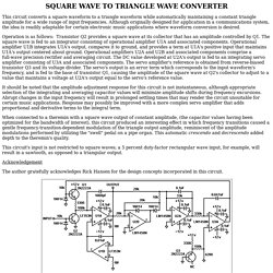
Although originally designed for application in a communications system, the idea is readily adaptable for certain electronic music applications where waveform conversion is desired. Operation is as follows: Transistor Q2 provides a square wave at its collector that has an amplitude controlled by Q1. The square wave is fed to an integrator consisting of operational amplifier U1A and associated components. Operational amplifier U1B integrates U1A's output, compares it to ground, and provides a term at U1A's positive input that maintains U1A's output centered about ground.
Operational amplifiers U2A and U2B and associated components comprise a full-wave precision rectifier and averaging circuit. Acknowledgement The author gratefully acknowledges Rick Hansen for the design concepts incorporated in this circuit.