
Mbed Audio Spectrum Analyzer Using the MSGEQ7. Introduction to the MSGEQ7 The goal of this project is to interface the MSGEQ7 7-Band Graphic Equalizer chip made by Mixed Signal Integration to the Mbed to create a 7-band Audio Spectrum Analyzer.
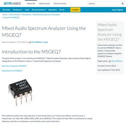
Sparkfun listing for MSGEQ7 Datasheet for MSGEQ7 The method in which this chip operates is that inside there are 7 band-pass filters, tuned to pass 7 frequencies: 63, 160, 400, 1000, 2500, 6250, and 16000 Hz. The output of each filter is connected to a peak detector, and then a multiplexer controlled by reset and strobe lines. At each falling edge of the strobe line, the outputs of the filter peak detectors are sequentially placed on the analog output line of the chip. Information Note that the analog output of the chip requires 36uS settling time after switching and before reading in order to get valid data. Interfacing with the MSGEQ7 MSGEQ7 Pinout In order to use the MSGEQ7, several external components are required. 2 - 100 nF Capacitors 1 - 10 nF Capacitor 1 - 33 pF Capacitor 1 - 200 kΩ Resistor.
LM3915 V2. Welcome to our site!
Electro Tech is an online community (with over 170,000 members) who enjoy talking about and building electronic circuits, projects and gadgets. To participate you need to register. Registration is free. Click here to register now. Dismiss Notice Forums Quick Links Recent Posts Articles Blogs Groups Members Useful Searches. Audio Millivoltmeter. Audio MillivoltmeterRod Elliott - ESP (Original Design) Introduction When performing any tests on an audio system, some form of measuring device is essential.
Digital multimeters are not useful, since they will not give the true picture of what is happening, and most have a fairly limited frequency range. An oscilloscope is the ideal tool, but not all hobbyists can afford the outlay for a scope, and would find justifying the not inconsiderable cost a tad difficult. An AC millivoltmeter - calibrated in dB - with a range of 30V down to 3mV full scale (80dB range) would be extremely useful.
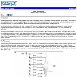
The meter presented here has a very wide frequency range, and uses a switched attenuator for range adjustment. The Attenuators The two attenuator networks are shown in Figures 1 and 2, and as you can see the Hi-Z version requires all those capacitors. Figure 1 - High Impedance Attenuator ( > 2M Ohm) Figure 2 - Low Impedance Attenuator ( > 200k Ohm) Amplifier. Project 140. True RMS Converter© Rod Elliott, 09 December 2012 Introduction Many AC waveforms we need to measure are not nice friendly sinewaves, and there is a significant error if you measure the value using a standard AC voltmeter.
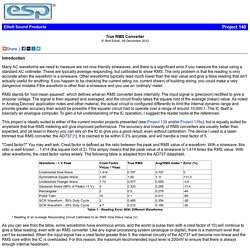
These are typically average responding, but calibrated to show RMS. The only problem is that the reading is only accurate when the waveform is a sinewave. Other waveforms typically read much lower than the real value and give a false reading that isn't actually useful for anything. RMS stands for 'root mean squared', which defines what an RMS converter does internally. This project is ideally suited to either of the current monitor projects presented (see Project 139 and/or Project 139a), but is equally suited for anywhere that true RMS metering will give improved performance. "Crest factor? " Table 1 - Reading Error With Different Waveforms * Reading of an Average Responding Circuit Calibrated to an RMS Sine Wave Value (V) Description.
Project 128-vu meter. Recording & Mixing Meter BridgeRod Elliott (ESP) Please Note: P87A PCBs are available for this project.
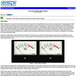
Click the image for details. Introduction Meter bridges are not as common as they once were, but are still an invaluable tool for any serious recording work. The analogue VU meter using a moving coil movement is still a commonly used meter, and even though true VU (Volume Unit) meters with calibrated ballistics (a measure of the needle's response to transients) are extremely expensive, comparatively cheap meters are still useful once you get used to them. Apart from anything else, the mechanical movement VU meter has a nice retro look to it that many people enjoy. Figure 1 - Typical Stereo VU Meters A high resolution image of the complete meter face is available. While some users may simply connect a VU meter directly across the output signal lines from the mixer, this approach will cause extra loading on the signal, which is non-linear.
Description Construction Testing Projects Index. Audio level meter circuit - VU Level Meter. Description A simple and low cost audio level meter circuit that can be used to measure the audio level of your sound source.This circuit is a valuable tool for those who are interested in audio circuits.
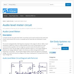
The circuit is designed with a flat frequency response in the range of 20Hz to 50Khz. Input sensitivity is 100mV for a FSD on a 100uA ammeter.The circuit is build based on on two common emitter amplifiers, the first stage has a preset resistor R3 (1K) which may be adjusted for a FSD. The last stage is biased to operate at about 1/2 the supply voltage for maximum AC voltage deflection. C2&C2 (10 uF) acts as a filters through which audio frequencies are passed . Audio Level Meter Circuit Diagram with Parts List Notes. We have more Audio Circuits that you may be interested in; 1. 2. 3. 4. 5.