
Rational software architect birt tutorial. IBM How to connect a required and provided interface in a composite structure diagram. Using IBM Rational Systems Developer V7.0.5, UPDM, and BIRT to produce DoD Architectural Framework views. Glossary UPDM: UML Profile for DoDAF and MoDAFDoDAF: Department of Defense Architectural FrameworkMoDAF: Ministry of Defence Architectural Framework BIRT: Business Intelligence and Reporting Tools Introduction to UPDM The UML Profile for DoDAF and MoDAF (UPDM) is an international standard accepted by the Object Management Group (OMG) in 2007.
UPDM provides an annotative mechanism by which UML or SysML models can describe enterprise architectures consistent with the DoDAF or MoDAF. The UPDM profile provides many stereotypes. The OV-6c is the DoDAF view that corresponds to the UPDM OperationalEventTrace. An OV-3, on the other hand, is the collection of UPDM InformationExchanges and their associated properties, and it is represented in tabular format. Three of these attributes enable the modeler to describe the information assurance, security, and transaction properties of that exchange.
Creating a simple UPDM model The scenario that we're using here is a hypothetical weather tracking system. Rational:Development Tools (RAD, RSA, RDA, RSM, RWD):Model wont open... - Development Tools (RAD, RSA, RDA, RSM, RWD) Forum. Generating UML models programmatically by using IBM Rational Software Architect. Why you may need to generate UML models programmatically The Unified Modeling Language (UML) has become a very widely adopted communication standard for software development projects around the world.
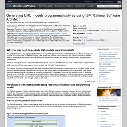
In software projects, UML models are currently used to describe and communicate about software artifacts, starting from requirements through application architecture, analysis, and design, to development, deployment and maintenance. However, in many situations, a project has information assets described in text format, and those assets need to be represented in UML to comply with best practices and to communicate with the rest of the project team. For example, business process analysts may have business process descriptions in text that need to be converted to UML activity diagrams before delivery to the application architecture and design team to use while designing the application. Importing MagicDraw models into Rational Software Architect 7.5.4: Truncated constraint bodies (and other attribute values) Problem(Abstract) When importing a UML 2.1 XMI model from MagicDraw into any of the Rational Software Architect 7.5.4 offerings, the values of some attributes can be incorrectly truncated at whitespace.
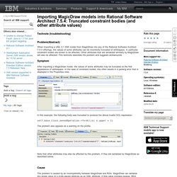
In particular, constraint bodies are known to be affected. Other attributes that are serialized similarly by MagicDraw will also be affected. This technote describes the problem and suggests workarounds. Symptom After importing a MagicDraw model, the values of some attributes may be truncated at the first appearance of whitespace. In this example, the following body was truncated to produce the above invalid OCL expression: Graphical Modeling Framework/Tutorial/Part 2. Customize using GMF Tooling diagram definition model files In this second part of the GMF Tutorial, some of the more advanced capabilities of the generation and runtime frameworks will be explored.
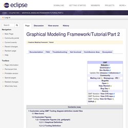
Specifically, information on adding compartments, connections, feature initializers, diagram validation, and nested child nodes will be covered. The complete solution to this tutorial is maintained in CVS here. Viewlets will be available after appropriate sections below to focus their content and keep them short. (warning: they are outdated) Important note: If you previously followed this tutorial with GMF 1.0, you'll need to be aware of changes in the graphical definition model described here. New Icons A quick way to get a polished look for our mindmap diagram is by replacing the generated EMF icons we've seen so far with some that are more, well... distinctive ;-) The easiest way to do this is to replace the GIF images found in our org.eclipse.gmf.examples.mindmap.edit/icons/ folder.
Shortcuts. Design Management V4: Any integration with SPARX EA? Release Date? - Jazz Forum. Introduction to UML2 Profiles. Copyright 2004, 2008 International Business Machines Corp.
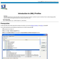
Summary This article describes how to work with profiles using the UML2 plug-ins for Eclipse. In particular, it gives an overview of how to create and apply profiles (and their contents) both programmatically and by using the sample UML editor Kenn Hussey, IBM (Updated: for Eclipse 3.4; James Bruck) Prerequisites To start using UML2 (and to follow along with the example in this article), you must have Eclipse 3.4, EMF 2.4, and UML2 2.2 installed. You can either download the zips individually and expand them out or follow the steps below: 1)Download and run Eclipse 3.4 2)Select the Help > Software Updates menu 3)Select the Available Software tab and expand the Ganymede\Model and Model Development tree item. Authoring UML Profiles: Part 2. Using Rational Software Architect, Rational Systems Developer, and Rational Software Modeler to manage change in UML Profiles.
Introduction This article is a detailed guide to the UML Profile Authoring support in the IBM® Rational® Software Architect, IBM® Rational® Systems Developer, and IBM® Rational® Software Modeler (Version 7.0 and later) products.
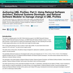
It covers both the UI support and programmatic support (for users extending the tool itself). It mainly targets profile authors, but it also offers some insight into profile usage. Authoring UML Profiles: Part 1. Using Rational Software Architect, Rational Systems Developer, and Rational Software Modeler to create and deploy UML Profiles. Introduction This article is a detailed guide to the UML Profile Authoring support in the IBM® Rational® Software Architect, IBM® Rational® Systems Developer, and IBM® Rational® Software Modeler (Version 7.0 and later) products.

It covers both the UI support and programmatic support (for users extending the tool itself). It mainly targets profile authors, but it also offers some insight into profile usage. Websphere - Can I develop Drools Rules Engine on IBM Rational Software Architect? IBM Importing MagicDraw models into Rational Software Architect 7.5.4: Truncated constraint bodies (and other attribute values) Microsoft Project integration with Rational Team Concert, Version 4.0. Sharoon Shetty Kuriyala, IBM Last updated: Nov 2012 Build basis: IBM Rational Team Concert 4.0 Some teams use Microsoft® Project for initial project planning while using IBM® Rational Team Concert™ for project tracking and execution.
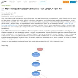
The import and export feature in Rational Team Concert allows the integration of project planning and tracking information between the two applications. You can import a Microsoft Project XML file to a plan in Rational Team Concert. In addition, you can export a Rational Team Concert plan to an XML file that can then be opened in Microsoft Project. The import and export feature uses the Microsoft Project XML file format that is described in Project XML Data Interchange Schema Reference. A plan in Rational Team Concert represents the work of a team/project for a particular iteration filed against a specific set of work item categories.