
Grid Paper PDFs. Free Online Graph Paper / Grid Paper PDFs Downloadable and very printable, I find these PDFs extremely useful.
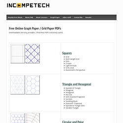
Tip number one! Though I do return the correct header for a PDF, sometimes Explorer gets confused when downloading... So if you're running Windows, you may need to right-click a link and choose "Save link to disk". Tip number two! Some people may need to turn off the option in Adobe's Acrobat reader "shrink to fit" which may resize the grid slightly to fit your printer's printable area. Tip number three! If you want the hexes aligned with the other edge of the paper, just make your paper size "11 x 8.5" and print the result in landscape mode!
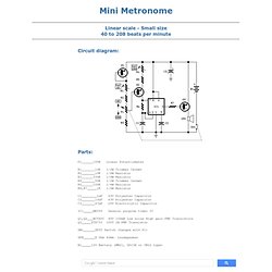
Translations Belorussian (provided by Ucallweconn weblog) Other. Figure & Gesture Drawing Tool. RED Free Circuit Designs - Audio. Mini Metronome - RED - Page8. Linear scale - Small size 40 to 208 beats per minute Circuit diagram: Parts: P1______100K Linear Potentiometer R1_______10K 1/2W Trimmer Cermet R2_______10K 1/4W Resistor R3______330K 1/4W Resistor R4_______50K 1/2W Trimmer Cermet R5______100K 1/4W Resistor R6,R7_____1K 1/4W Resistor C1________1µF 63V Polyester Capacitor C2_______10nF 63V Polyester Capacitor C3_______47µF 25V Electrolytic Capacitor IC1_____NE555 General purpose timer IC Q1,Q2___BC560C 45V 100mA Low noise High gain PNP Transistors Q3_____ZTX753 100V 2A PNP Transistor SW1______SPST Switch (Ganged with P1) SPK______8 Ohm 40mm.
Loudspeaker B1_____12V Battery (MN21, GP23A or VR22 type) Precision Metronome and Pitch generator - RED - Page3. Circuit diagram: Parts: Circuit operation: CMos IC1 and IC2B quad AND gate form a 2.4576 MHz crystal oscillator plus a 2400 times divider.
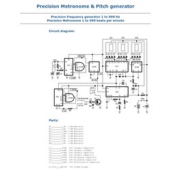
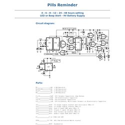
IC3A provides further division by 16, delivering a 64 Hz stable frequency square wave. This frequency is multiplied (by means of Phase Locked Loop IC5, double decade divider IC4 and IC3B 4 bit binary divider) by the number set by three miniature BCD thumbwheel switches SW1, SW2 and SW3: units, tens and hundreds respectively. Pills Reminder - RED - Page143. Circuit diagram: Parts: R1______________10M 1/4W Resistor R2,R3,R4_______100K 1/4W Resistors R5,R7___________10K 1/4W Resistors R6_______________1K 1/4W Resistor C1,C2___________22pF 63V Ceramic Capacitors (See Notes) C3______________22µF 25V Electrolytic Capacitor C4,C5__________100nF 63V Polyester Capacitors C6_______________1µF 63V Polyester, Multilayer Ceramic or Electrolytic Capacitor IC1____________4060 14 stage ripple counter and oscillator CMos IC IC2____________4040 12 stage ripple counter CMos IC IC3____________4082 Dual 4 input AND gate CMos IC IC4____________4075 Triple 3 input OR gate CMos IC IC5____________4520 Dual binary up-counter CMos IC IC6____________4001 Quad 2 input NOR Gate CMos IC D1_____________5 or 10mm red LED XTAL_________32.768 kHz Sub-miniature Watch crystal P1_____________SPST Pushbutton SW1____________2 poles 6 ways Rotary Switch SW2____________SPST Toggle or Slide Switch B1_______________9V PP3 Battery Clip for PP3 Battery Alternative Clock Parts:
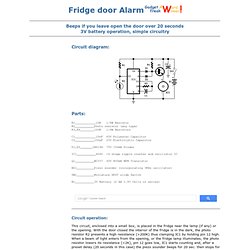
Fridge door Alarm - RED - Page15. Circuit diagram: Parts: R1____________10K 1/4W Resistor R2___________Photo resistor (any type) R3,R4________100K 1/4W Resistors C1____________10nF 63V Polyester Capacitor C2___________100µF 25V Electrolytic Capacitor D1,D2_______1N4148 75V 150mA Diodes IC1___________4060 14 stage ripple counter and oscillator IC Q1___________BC337 45V 800mA NPN Transistor BZ1__________Piezo sounder (incorporating 3KHz oscillator) SW1__________Miniature SPST slide Switch B1___________3V Battery (2 AA 1.5V Cells in series)
Whistle Responder - RED - Page29. Circuit diagram: Parts: R1_____________22K 1/4W Resistor R2_____________10K 1/4W Resistor R3______________4M7 1/4W Resistor R4,R8_________100K 1/4W Resistors R5____________220R 1/4W Resistor R6____________330K 1/4W Resistor R7_____________47K 1/4W Resistor R9______________2M2 1/4W Resistor R10_____________1M5 1/4W Resistor C1,C5__________47nF 63V Polyester or Ceramic Capacitors C2,C3__________10nF 63V Polyester Capacitors C4,C6___________1µF 63V Electrolytic Capacitors D1,D2________1N4148 75V 150mA Diodes IC1____________4049 Hex Inverter IC Q1____________BC337 45V 800mA NPN Transistor MIC1_________Miniature electret microphone BZ1__________Piezo sounder (incorporating 3KHz oscillator) B1___________2.8 or 3V Battery (see notes) Device purpose: Some 20 years ago it was common to see small key-holders emitting an intermittent beep for a couple of seconds after its owner whistled.
These devices contained a special purpose IC and therefore were not suited to home construction. One-IC two-tones Siren - RED - Page5. Circuit diagram: Parts: R1,R3___470K 1/4W Resistors R2______680K 1/4W Resistor R4_______82K 1/4W Resistor R5______330K 1/4W Resistor R6_______10K 1/4W Resistor R7_______33K 1/4W Resistor R8________3M3 1/4W Resistor C1,C5_____10µF 25V Electrolytic Capacitors C2,C6_____10nF 63V Polyester Capacitors C3_______100nF 63V Polyester Capacitor C4_______100µF 25V Electrolytic Capacitor D1-D3___1N4148 75V 150mA Diodes IC1_____4093 Quad 2 input Schmitt NAND Gate IC Q1______BC337 45V 800mA NPN Transistor P1______SPST Pushbutton SW1_____DPDT Switch SPKR____8 Ohm Loudspeaker B1______6V Battery (4 AA 1.5V Cells in series) Circuit operation: This circuit is intended for children fun, and can be installed on bicycles, battery powered cars and motorcycles, but also on models and various games and toys.
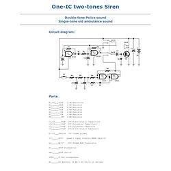
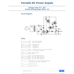
With SW1 positioned as shown in the circuit diagram, the typical dual-tone sound of Police or Fire-brigade cars is generated, by the oscillation of IC1A and IC1B gates. Variable DC Power Supply - RED - Page36. Circuit diagram: Parts: P1____________500R Linear Potentiometer P2_____________10K Log.
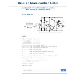
Quick on-board Junction Tester - RED - Page133. Circuit diagram: Parts: R1,R9,R11,R12__100K 1/4W Resistors R2,R3,R6________10K 1/4W Resistors R4,R5,R10_______47K 1/4W Resistors R7_______________1M 1/4W Resistor R8_______________1M5 1/4W Resistor C1_____________100nF 63V Polyester Capacitor C2_______________1µF 63V Polyester or Multilayer Ceramic Capacitor C3,C4___________10µF 25V Electrolytic Capacitors D1____________1N4148 75V 150mA Diode Q1_____________BF245 or 2N3819 General-purpose N-Channel FET IC1____________LM358 Low Power Dual Op-amp BZ1____________Piezoelectric sounder (incorporating 3KHz oscillator) SW1____________SPST Toggle or Slide Switch Red Probe______Insulated probe, Multimeter-like Black Probe____The same as above B1______9V PP3 Battery Clip for PP3 Battery Comments: Short circuits or broken pcb tracks can be easily recognized by means of a Multimeter, but this tool can give wrong results when testing the efficiency of a transistor or diode, unless the device under test is unsoldered and removed from the pcb.
Circuit Board Tester - RED - Page130. Circuit diagram: Parts: R1,R2___________22K 1/4W Resistors D1______________LED (Any dimension and shape, preferably red) D2______________LED (Any dimension and shape, preferably green) Q1____________BF245 or 2N3819 General-purpose N-Channel FET Q2____________BC547 45V 100mA NPN Transistor Q3____________BC557 45V 100mA PNP Transistor Probe_________Metal Probe 3 to 5 cm. long Two Miniature Crocodile Clips (Red and Black) Comments: This little circuit indicates the basic integrity of a printed board, detecting 0V, positive supply voltage from less than 3V to 30V and floating parts.
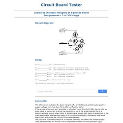
If the probe is floating, as it would be in a broken track, then both LEDs barely light up, since there is no current to drive the transistors, but if the probe touches 0V or a positive voltage one or other lights. Self-powered Fast Battery-Tester - RED - Page43. Circuit diagram: Parts: R1______________2K2 1/4W Resistor R2______________3R3 1/4W Resistor R3_____________10R 1/4W Resistor R4______________4K7 1/4W Resistor R5_____________33K 1/4W Resistor R6,R7_________100K 1/4W Resistors R8____________220K 1/4W Resistor R9____________330K 1/4W Resistor R10___________500K Trimmer Cermet C1,C2__________10nF 63V Polyester Capacitors C3-C7_________100nF 63V Polyester Capacitors C8____________220µF 35V Electrolytic Capacitor D1,D7___________LEDs Red 5mm.
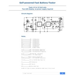
(see Notes) D2-D6________1N4148 75V 150mA Diodes Q1___________2N3819 General purpose FET Q2,Q3_________BC337 45V 800mA NPN Transistors IC1,IC2________7555 or TS555CN CMos Timer ICs P1_____________SPST Pushbutton SW1____________DPDT Switch BUT____________Battery under test Holder or clips to connect the Battery under test to the circuit Device purpose: This circuit runs a fast battery test without the need of power supply or expensive moving-coil voltmeters. Ultra-simple Voltage Probe - RED - Page25. Circuit diagram: Parts: D1________5 or 3mm. Red LED D2________5 or 3mm.
Green or Yellow LED LP1_______220V 6W Filament Lamp Bulb P1________Red Probe P2________Black Probe. Speech Amplifier Box - RED - Page121. Circuit diagram: Parts: P1______________22K Log. Potentiometer R1_______________1M 1/4W Resistor R2______________15K 1/4W Resistor R3_____________470R 1/4W Resistor R4______________47K 1/4W Resistor R5,R6____________4K7 1/4W Resistors (Optional, see Notes) C1,C2,C4_______100nF 63V Polyester or Ceramic Capacitors C3______________10nF 63V Polyester or Ceramic Capacitor (See text) C5_____________220µF 25V Electrolytic Capacitor C6______________10µF 25V Electrolytic Capacitor (Optional, see Notes) Q1____________BC547 45V 100mA General purpose NPN Transistor IC1_________TDA7052 Audio power amplifier IC J1______________3mm or 6mm Mono Jack socket SW1____________SPST Slider Switch fitted in the microphone (Optional, see text) SW2____________SPST Toggle or Slider Switch SPKR______________4-8 Ohm Loudspeaker (See Notes) B1_______________6V Battery (4 x AA or AAA 1.5V Cells in series or any 6V rechargeable battery pack etc.)
Sleeping-Aid - RED - Page48. Circuit diagram: Parts: R1,R5___________1K 1/4W Resistors R2_____________10K 1/4W Resistor R3,R6__________10M 1/4W Resistors R4,R7___________2M2 1/4W Resistors R8,R9___________4K7 1/4W Resistors C1,C7__________47µF 25V Electrolytic Capacitors C2____________100nF 63V Polyester Capacitor C3,C4_________330nF 63V Polyester Capacitors C5,C6__________15nF 63V Polyester Capacitors D1,D3,D4,D5__1N4148 75V 150mA Diodes D2______________LED (any type) (see Notes) IC1____________4060 14 stage ripple counter and oscillator IC IC2____________4093 Quad 2 input Schmitt NAND Gate IC Q1____________BC327 45V 800mA PNP Transistor L1____________Radiator coil (see Notes) P1____________SPST Pushbutton SW1___________2 poles 4 ways rotary switch SW2___________SPST Slider Switch B1____________9V PP3 Battery Clip for PP3 Battery Features: Generates a natural electromagnetic-fieldMakes easier to fall asleepInduces a prolonged and sound sleep without drugsNo side effects.
Rain sound effect Generator - RED - Page75. Circuit diagram: Parts: Comments: Sound effects generators trying to imitate rain sound or sea surf are well known to hobbyists from many years: their purpose is to induce relaxation and sleep or to help in concentration and study. The sound generated is restrained to a background level and these devices are frequently kept on the night table. Common designs use invariably Zener diodes or reverse-biased transistors base-emitter junctions as white noise generators. Full-duplex Intercom - RED - Page78. Amplified Ear - RED - Page38. Automotive Voltage Indicator - RED - Page115. Car Battery Saver - RED - Page153. Headlights Timer - RED - Page79. Push-bike Light - RED - Page98. Bicycle back Safety Light - RED - Page24. Jogging Timer - RED - Page32. Digital Step-Km Counter - RED - Page9. Brightness Control for small Lamps - RED - Page63. Bedside Lamp Timer - RED - Page4. Courtesy Light - RED - Page27.
Dark-activated LED or Lamp Flasher - RED - Page64. Temperature-controlled Fan - RED - Page70. TED: Ideas worth spreading. Figure 1.
Beginning Engineers Checklist. Electronic Circuit Theory. Wire Capacity Chart. Schematic Symbol Reference. Index of /pcbstandards. Electronic circuit diagram database. Free Electronic Circuits. Free Electronic Circuit Diagrams Directory. Sample autocad drawings. AutoCAD Sample Drawings. Sample Drawing Files. 3D Warehouse. Associates - Transformable Design.
SupportNet Overview. Galleries - Starfleet Bridge Illustrations. Intrepid Class. Voyschembot.jpg (JPEG Image, 1355x734 pixels) - Scaled (44%) Schematics star trek. Outpost 10F Schematics - Star Trek Schematics - Star Wars Schematics - Sci Fi Schematics. Starship Schematic. Star Trek LCARS Blueprint Database - Gilso's Star Trek Schematics. Gilso Star Trek Schematics Main Page.