Zuzebox's Blog. Raspberry Pi (Beeb) UserPort HAT November 30, 2014 Of the recent Pi boards I’ve made I think UserPort is probably my favourite.
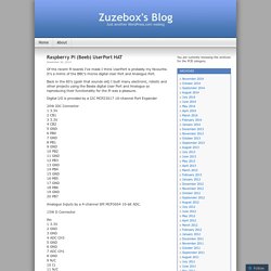
It’s a mimic of the BBC’s micros digital User Port and Analogue Port. Back in the 80’s (gosh that sounds old) I built many electronic, robotic and other projects using the Beebs digital User Port and Analogue so reproducing their functionality for the Pi was a pleasure. Digital I/O is provided by a I2C MCP23017 16-channel Port Expander 20W IDC Connector 1 3.3V 2 CB1 3 3.3V 4 CB2 5 GND 6 PB0 7 GND 8 PB1 9 GND 10 PB2 11 GND 12 PB3 13 GND 14 PB4 15 GND 16 PB5 17 GND 18 PB6 19 GND 20 PB7. The Impossible Tribar: Light Seeking Robot V1-V4.1. Thiem-Work.
Wireless Camera with Arduino and the CC3000 WiFi chip. One nice thing to have in any home automation or alarm system is a camera to see what’s going on remotely.
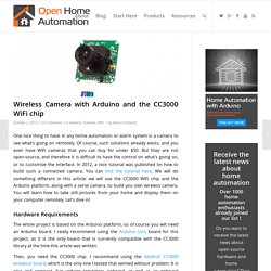
Of course, such solutions already exists, and you even have WiFi cameras that you can buy for under $50. But they are not open-source, and therefore it is difficult to have the control on what’s going on, or to customize the interface. In 2012, a nice tutorial was published on how to build such a connected camera. You can find the tutorial here. We will do something different in this article: we will use the CC3000 WiFi chip and the Arduino platform, along with a serial camera, to build you own wireless camera. Hardware Requirements The whole project is based on the Arduino platform, so of course you will need an Arduino board. Project Lab. Difficulty Level = 7 [What's this?]
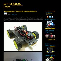
I built a remote-controlled robotics platform using a 4WD mobile platform, an Arduino (Seeeduino Mega), an Adafruit motor shield, and two XBee radios for communication. There are also some super-bright white LEDs on the front for headlights. The point of the project was to show how an XBee radio can be used to send joystick sensor data without using a microcontroller on the remote. The vehicle is very easy to control using a joystick and a couple of buttons to control the lights. First I’ll describe how the remote control unit works, then I’ll show how the vehicle was built. The Remote.
Custom PCB for DIY electronics. Constant-Q Graphic Equalizers. Dennis Bohn, Rane Corporation RaneNotes 101 & 117 combined; written 1982 & 1987; last revised 11/05 Introduction Few would argue the necessity of equalizers for quality sound reinforcement systems.
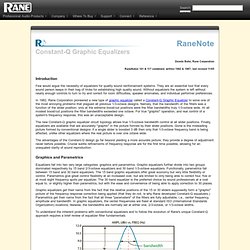
They are an essential tool that every sound person keeps in their bag of tricks for establishing high quality sound. Without equalizers the system is left without nearly enough controls to turn to try and correct for room difficulties, speaker anomalies, and individual performer preferences. Expandable Graphic Equaliser. Expandable Graphic EqualiserRod Elliott (ESP) [1] Introduction The project described in this article is a constant Q, fully expandable graphic equaliser.
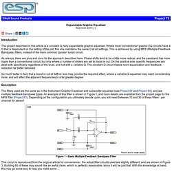
Where most 'conventional' graphic EQ circuits have a Q that is dependent on the setting of the pot, this one maintains the same Q at all settings. This is achieved by using MFB (Multiple Feedback Bandpass) filters, instead of the more common 'gyrator' tuned circuit. As always, there are pros and cons for the approach described here. So much better in fact, that a boost or cut of 3dB or less may provide the required effect, where a variable Q equaliser may need considerably more, and will affect the adjacent frequencies to a far greater degree. Description. Amplifier Circuit. Amplifier Circuit. 5-Band Fully Parametric EQ.
Just a quick question, why do you need 4 opamps (2 x NE5532) in the "signal path"?
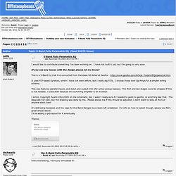
Isn't IC1B and IC2A sufficient? Yes they are sufficient. However, the person that prompted me to design this wanted dual inputs, and I wanted Input and Output Trimmers. Stalker_radiokot nexie на ИН-12. Проект ИН-12. КАШАК Nixie clock модификация. Начинка для часов на лампах ИН-8-2 и ИН-14 / Наши пользователи / Блошиный рынок. Build a Nixie-tube clock. Adafruit NeoPixel Überguide. Incorporating scads of LEDs into an electronic project used to be a hairy prospect, a veritable rat’s nest of wires and code.
The arrival of dedicated LED driver chips brought welcome relief, offloading grunt work from the microcontroller and allowing one to focus on the application. Much simpler, but still not “Christmas light” simple. The WS2812 Integrated Light Source — or NeoPixel in Adafruit parlance — is the latest advance in the quest for a simple, scalable and affordable full-color LED. Red, green and blue LEDs are integrated alongside a driver chip into a tiny surface-mount package controlled through a single wire. Proto Shield for Arduino. This is a design for an open-source prototyping shield for Arduino NG/Diecimila.
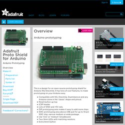
It has tons of cool features, to make prototyping on your Arduino easy. Compatible with NG, Diecimila, Duemilanove and any Arduino-clone in the 'classic' shape and pinout.Reset button up topICSP headerLots of GND and +5V rails.DIP prototyping area makes it easy to add more chips.SOIC prototyping area above USB jack for up to 14-pin SOIC chip, narrow medium or wide package.Use 'mini' or 'medium' breadboard.Two 3mm LEDs with matching resistors.Extra 6mm button Ideas for use Larger breadboard for tons of working space! Tiny breadboard fits nicely on top. 2 LEDs and one button are availble for general purpose use! Untitled. Тимофей Носов 25 мая 2014 г.