
ARDUINO MPPT SOLAR CHARGE CONTROLLER (Version-3.0) After lot testing we observed that MOSFET ( Q3 ) in ver-3.0 design is burning repeatedly.We tried to modify the existing software but not find any satisfactory result. The other problem was that MOSFET Q1 ( in V-3.0) conduct even when there is no solar input. To solve the above problems and enhance the power handling capability we are modifying both the hardware and software.This is named as Version-3.1 Charge Controller. This version is not completed yet.So wait until it is complete. Don't worry we are making a solution for those who have made the V-3.0 prototype.After little modification we will able to use the new software. You can see the updates on Hackaday.com This version have 3 options. 1. 5 Amp version : T94-26 toroid, 48 turns of AWG20 wire to give 135 uH (it takes almost 1.5m of wire) Q1, Q2 and Q3 all pairs of IRFZ44N MOSFETs (6 in all). C1 will be 3 * 220 uF low ESR capacitors in parallel, C2 will be a single 220 uF low ESR capacitor 2. 8 Amp version : 3 10 Amp version :
BLDGBLOG OpenUPS OpenUPS The OPEN-UPS was designed to provide user specified regulated power output from a wide input voltage, battery backup, multi-chemistry charging and cell balancing in a single PCBA. The unit automatically switches the power path in between Battery and Main DC input and provides buck/boost output regulation. OpenUPS has strong Windows / Linux support and API allowing developers to interface to custom applications. Open-UPS provides the following features: - Intelligent UPS, USB interface, SMBUS slave and I2C master. - Input 6-30V, Programable output 6-24V. - Li-Ion, Li-Po, LIFEPO4, Lead Acid. - Fuel Gauge. OpenUPS cables included: Battery Cable- End_1: mini-FIT JR receptacle 1x2pos- End_2: Cut wire- Wire: Yellow / Black AWG 16- Yellow wire close to the mini-FIT JR latch Cable2 (Battery Balance Cable)End_1 JST PH connector, 5pinEnd_2 Cut wireAWG 26 wire colors:- POS1=Yellow- POS2=Red- POS3=Blue- POS4=White- POS5=Violet Cable32pin-2pin - 210mm Cable4,52 x P4-12V to P4-12V Cable (200mm)
DIY thermoelectric device charges hiker's smartphone (Phys.org) —Whether you're in a city café hunting down a spare outlet or camping and worrying about losing outside contact, the problem is the same, a smartphone about to lose power just when you need it the most. What to do? A problem-solver who is into hiking and backpacking has an answer. He shows, step to step, how to construct a portable thermoelectric emergency generator. David Johansson, who used the project-sharing site Instructables for his step by step instructions, explained how he arrived at the idea, construction, and results. Spending several days hiking in the wild at times, he would rely on his smartphone with GPS, along with spare batteries and solar chargers. "The sun in Sweden is not very reliable," he wrote. Error loading skin: Error loading file In thinking up alternatives, he considered the idea of producing electricity from heat for USB gadgets. "I´m using a thermoelectric module, " he said, "also called Peltier element, TEC or TEG."
EcoRenovator - View Single Post - DIY ventilation heat exchanger Thanks Ryland A small air-air heat pump (like an old A/C unit) could be hooked up after the heat exchanger, increasing the amount of heat transfered, or reducing the temp difference on both sides of the AC, depending on how you look at it. In fact, there will already be a heat pump in the system we are planning, it will transfer heat from waste air to the hot water tank. I looked around and found a few pics. And here is how it works: Here is a homemade plywood construction that uses 2 cross-flow recuperators in a counter-current set-up (increasing efficiency): Here's the inside of a large area, counter-current heat exchanger: It is made of scores of thin sheets of copper or aluminum, stacked 4-5mm apart. Here is a pictures of someone's finished project: You can see the smaller diameter bypass for when you do not want to lose/gain heat.
solar-thermal electric generator Initial idea by Miriam EnglishAlina Friedrichsen - suggested using DS1820 for temperature measurement, and Inkscape for SVG diagrams, also pointed to some ways to program Linux to read ports. If you want to make suggestions then feel free to comment at my blog. Soon I hope to be able to add comments directly to the bottom of this page. The neat thing about this is that it gets around one of the major limitations of solar photovoltaic panels, that they only work during daylight. None of this is secret, in fact when I am finished building and testing it I'll publish all data on the net for anybody who wants to build one too. It uses the thermoelectric effect, but approaches it a slightly different way than usual. It is easiest to understand by starting at the bottom of the diagram. A solar heating panel is filled with water. Above the hot storage tank is another well-insulated tank, also containing water. or else semiconductor peltier cooler modules can be used. Modifications Measurement
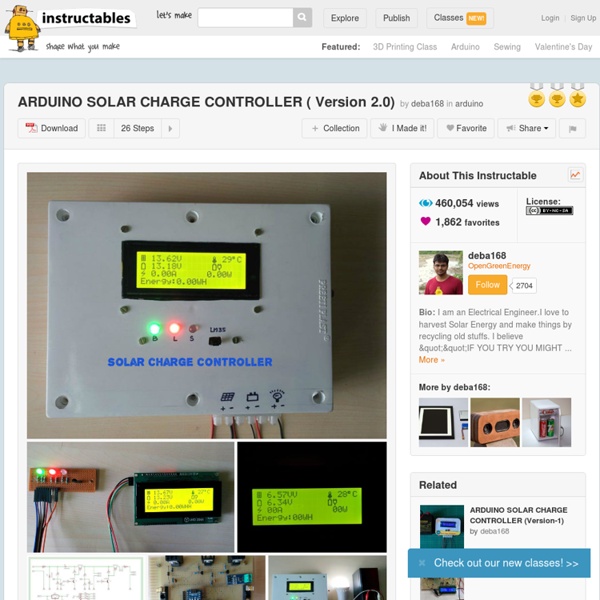
Hacked Gadgets – DIY Tech Blog deba168 from India designed and built this Arduino Solar Charge Controller to provide electrical power in areas where the grid can’t always provide power when needed. Code and schematics are provided so you can get some inspiration from the design. ”At first the charge controller will check the solar panel voltage and compare it with battery voltage ,If it is greater then the Arduino will starts sending pulse width modulation(PWM) signals to the mosfet(Q1) in order to charge the battery .When the solar panel voltage was below the battery voltage ,this pwm signals will not send by Arduino . Then next the micro controller will check the battery voltage ,if the battery voltage was below 6.96 v volts then the battery will be charged in boost mode ,that mean the battery will be charged with maximum amperage ,this boost mode of charging will be done by sending pulse width modulation signals with 95% duty cycle .
These Satellite Images of Earth "Breathing" Are Freaking Me Out It freaks me out that tiny atoms and huge solar systems consist of things rotating around each other in a similar way. It's also weird to see time-lapse footage of human beings building things (like that super-fast hotel build in China) and realize how insectoid our activities look when sped up. And above you see the latest strange big/small connection: The planet Earth resembling a beating heart or a breathing being. A guy named John Nelson runs the UX Blog, which covers user experience, mapping and data visualization for parent software company IDV Solutions. Nelson pulled twelve rare, unobscured-by-clouds images of our planet off of NASA's Visible Earth catalog taken at different times of the year. Stitching them together into an animation, he made the visually stunning discovery you see here: As the seasons change, the ebb and flow of snow and greenery makes our little rock look like it's breathing. There's one thing, however, that we're on the same page about.
Test of power supply DPS5015 Power supply frontend DPS5015 50V/15A This device is the front end for a power supply, it must be supplied with low voltage DC power (Up to 60V). Official specifications: Input voltage range: 6.00-60.00V Output voltage range: 0V-50.00V Output current: 0-15.00A Output power range: 0-750W Product Weight: about 222g Display module size: 79*43*41(mm) (L*W*H) Open size: 71mm*39mm Power module size: 93*71*41(mm) (L*W*H) Length of connecting line: 200mm Fixed hole center distance: 86mm, 64mm Output voltage resolution: 0.01V Output current resolution: 0.01A Output Voltage accuracy: ± (0.5% + 1 digit) Output Current accuracy: ± (0.5% + 2 digits) I got it from aliexpress store: RD official store It arriwed in a styrofoam box, inside the box was the plastic box with the electronic. There is a control unit, a power unit, two cables, some rather small fork terminals and a manual in English and Chinese. The control unit has a nice display, four buttons and a encoded that can be pressed. Measurements
Float charging lithium ion cells Apart from making better door stops, what advantage do lead-acid batteries have over lithium ion (Li-ion) batteries? The answer is that they are easier to charge. Apply 13.8V to any nominally 12V lead-acid battery and it will take just the current needed to keep itself in tip top condition, and it will be ready to deliver its full capacity instantly. Applying a constant potential is called ‘float charging’ and lead-acid batteries are almost perfectly suited to it. While more expensive per Watt-hour, lithium-ion cells are far lighter, smaller and contain fewer toxic chemicals than most other commonly available battery types. “This is because Li-ion is mostly used for cycle applications where the main goal of the customer is to recharge as fast as possible,” says Antoine Brenier, business development manager at French battery-maker Saft. What needs to be borne in mind when connecting a Li-ion cell permanently to a power source is that they have no recombination ability. Tags:power sources
untitled The Compact Door has been designed to incorporate the advantages of both Roller Shutter and Overhead Sectional Doors and to overcome their inherent disadvantages. What makes the Compact door different from all other Industrial doors is its unique patented rail system. On opening the door panels fold upwards into a compact space above the door similar to a roller shutter. However, unlike a roller shutter the Compact Door panels are insulated and can also be fully glazed. A wicket door can be built into the door panels if required. The smooth and quiet movement of the panels uses little energy this guarantees a longer life cycle and lower maintenance costs. The Compact door is self supported from its side rail system and does not have intrusive overhead rails and balancing springs required by sectional doors. A comprehensive web based design programme is available to the Architect/Designer.