
DC to DC Converters. Automatic 12V Lead Acid Battery Charger. Solaris Power Systems. System Features The Sentinel system uses one Monitor, with the option of Measurement Modules (voltage measurement) or the m‐Senzor (voltage and ohmic measurement).

Voltage monitoring will identify incorrect charge voltage and faults such as a short circuit in a battery/jar, which causes a drop in voltage. Capacity is determined through a discharge test. Applicable for vented batteries/jars or entry level monitoring for VRLA batteries/jars where regular testing is undertaken. The base m‐Senzor provides voltage and soon to be introduced ambient temperature near the battery/jar. Solaris Power Systems. Sizing a Battery Charger Battery Chargers should be large enough to power the normal system loads while recharging a discharged battery within a reasonable amount of time.
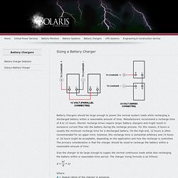
Manufacturers recommend a recharge time of 8 to 12 hours. Shorter recharge times require larger battery chargers and might result in excessive current flow into the battery during the recharge process. For this reason, 8 hours is usually the minimum recharge time for a discharged battery. On the high end, 12 hours is often recommended for an upper limit; however, this recharge time is somewhat arbitrary and 14 hours or 16 hours might be acceptable, depending on the application and how the recharge is controlled.
Size the charger to be large enough to supply the normal continuous loads while also recharging the battery within a reasonable time period. Where: A = Output rating of the charger in amperes. k = Efficiency factor to return 100 percent of ampere hours removed. Battery Charging Tutorial. Current battery charging technology relies on microprocessors (computer chips) to recharge, using 3 stage (or 2 or 4 stage) regulated charging.

These are the "smart chargers", and quality units generally are not found in discount stores. The three stages or steps in lead/acid battery charging are bulk, absorption, and float. Qualification, or equalization are sometimes considered another stage. A 2 stage unit will have bulk and float stages. It is important to use battery manufacturer's recommendations on charging procedures and voltages, or a quality microprocessor controlled charger to maintain battery capacity and service life. The "smart chargers" are profiled with contemporary charging philosophy in mind, and also take information from the battery to provide maximum charge benefit with minimum observation. Most battery manufacturers recommend sizing the charger at about 25% of the battery capacity (ah = amp hour capacity). Three Stage Battery Charging. Www.battcon.com/PapersFinal2009/SalanderPaper2009FINAL_15.pdf.
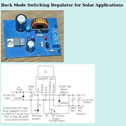
Lead Acid Battery Charger Circuit. Buck Mode Switching Regulator for Solar Applications. (C) G.
SCC3 20A 12V Solar Charge Controller Electronic Circuit - CircuitsArchive. Introduction The SCC3 is a solar charge controller, it's function is to regulate the power flowing from a photovoltaic panel into a rechargeable battery.
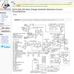
It features easy setup with one potentiometer for the float voltage adjustment, an equalize function for periodic overcharging, and automatic temperature compensation for better battery charging over a wide range of temperatures. The design goals of this circuit were efficiency, simplicity, reliability, and the use of field replaceable parts. A medium power solar system can be built with the SCC3, a 12V solar panel that is rated from 100 milliamps to 20 amps, and a lead acid or other rechargeable battery that is rated from 500 milliamp hours to 400 amp hours of capacity. It is advisable to match the solar panel's maximum current to the battery's amp-hour rating (C), a typical battery charging current is C/20, so a 100 amp hour battery should have a solar panel rating of around 5 amps.
Specifications Theory. DC/DC Converters, to convert voltage up or down, retail, wholesale, off-the-shelf and custom, DC/DC 5 watts to 1500 watts, voltage from 1.5V to 72V, DC/DC power supplies. Resources.mini-box.com/online/PWR-M4-ATX/PWR-M4-ATX-manual.pdf. Www.formfactors.org/developer/specs/atx2_1.pdf. ATX Computer Power Supply Pinout and Connectors. Note that all voltages are referenced to the same common (if you need to measure any voltage, connect the return lead of your voltmeter to any of the COM contacts).
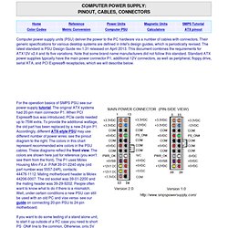
Also note that many brands such as Apple's Power Mac, Dell (during certain years), Compaq and HP had proprietary boards with entirely different pin designations- see this for info on some brand name power supplies. The rated current of the main Molex connector is 6A per contact. This means with the old 20-pin style you can't get more than 18A from 3.3V and 24A from 5V. That's why in early 2000's, some motherboards with 3.3V >18A and 5V >24A (mainly dual CPU AMD systems) used an auxiliary 6-pin power cable. It was removed from ATX12V spec v2.0 in 2003 because extra wires were added to P1.
Electronic Components Distributor. Free PCB layout software - Low cost circuit boards - Top quality PCB manufacturing. Buck-Converter Design Demystified Page of. Stepdown (buck) switching converters are integral to modern electronics.
They can convert a voltage source (typically 8 V to 25 V) into a lower regulated voltage (typically 0.5 V to 5 V). Stepdown converters transfer small packets of energy using a switch, a diode, an inductor and several capacitors. Though substantially larger and noisier than their linear-regulator counterparts, buck converters offer higher efficiency in most cases. Despite their widespread use, buck-converter designs can pose challenges to both novice and intermediate power-supply designers because almost all of the rules of thumb and some of the calculations governing their design are hard to find. ProCooling.com. Let me explain the schematic (or circuit diagram, whatever you want to call it).

The ICs on the board are Analog Devices ad1193 FET drivers (U1 and U2); these connect to the gate of the N-Channel mosfet (International Rectifier IRF 1407, M1 and M2). The 15V zener diode (D1 and D2) is just protection, to make the circuit a little safer. The FET drivers take in 12v, and turn it into 18v at a very low current, saturating the mosfet gates beyond the VGS barrier (Vs + 4). This lets the mosfet act like a very low ohm resistor, and restricts the current very little. It may produce a little heat, but it is not much (your sound card will more than likely put out more heat than this will ;) ). The trademark of this circuit, one of the things that sets it apart is the use of the mosfets positive temperature coefficient. In comparison to other methods, the numbers would say that it is quite superior. Hot Swap Power Management - ORing Controller - TPS2410. The TPS2410/11 controller, in conjunction with an external N-channel MOSFET, emulates the function of a low forward-voltage diode.
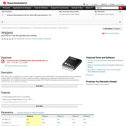
The TPS2410/11 can be used to combine multiple power supplies to a common bus in an N+1 configuration, or to combine redundant input power buses. The TPS2410 provides a linear turn-on control while the TPS2411 has an on/off control method. Applications for the TPS2410/11 include a wide range of systems including servers and telecom. M4-ATX Automotive Power Supply. Free Shipping Logic Supply offers Free Economy Shipping within the United States on all online orders of $250 and above.
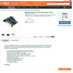
If your purchase qualifies for Free Economy Shipping, you will see this option available at the time of checkout. We only offer Free Economy Shipping to orders shipped within the lower 48 states of the US (excludes Hawaii and Alaska). For Canadian and International customers, we have an Economy Shipping option available via USPS on certain products. For smaller components, this can help reduce overall shipping costs. For European customers, we have a website and store located in the EU at www.logicsupply.eu. All about the various PC power supply cables and connectors. Last updated: July 15, 2008 All about the various PC power supply cables and connectors The various power supply cables General info. 12 Volt 30 Amp Power Supply. Circuit : Andy CollinsonEmail : Description Using a single 7812 IC voltage regulator and multiple outboard pass transistors, this power supply can deliver output load currents of up to 30 amps.
The design is shown below: