
Sparx Systems - UML 2 Tutorial. UML 2 advances the successful UML specification, and is quickly becoming the accepted standard for specifying, documenting and visualizing software systems.
The Unified Modeling Language (UML) is also used for the modeling of non-software systems, and is extensively implemented in most industry sectors including finance, military and engineering. If you are new to the Unified Modeling Language, our Introduction to UML is a recommended starting point. UML is divided into two general sets and includes fourteen basic diagram types: 1. Structural Modeling Diagrams Structure diagrams define the static architecture of a model. 2. Behavior diagrams capture the varieties of interaction and instantaneous states within a model as it 'executes' over time; tracking how the system will act in a real-world environment, and observing the effects of an operation or event, including its results. UML - Building Blocks. As UML describes the real time systems it is very important to make a conceptual model and then proceed gradually.
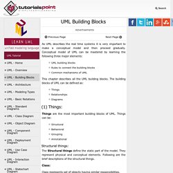
Conceptual model of UML can be mastered by learning the following three major elements: UML building blocksRules to connect the building blocksCommon mechanisms of UML This chapter describes all the UML building blocks. The building blocks of UML can be defined as: ThingsRelationshipsDiagrams (1) Things: Class Diagram Relationships in UML with ExamplesCreately Blog. Many people consider class diagrams a bit more complicated to build compared with ER diagrams.
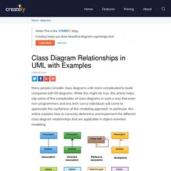
While this might be true, this article helps clip some of the complexities of class diagrams in such a way that even non-programmers and less tech-savvy individuals will come to appreciate the usefulness of this modeling approach. In particular, this article explains how to correctly determine and implement the different class diagram relationships that are applicable in object-oriented modeling. The UML Class Diagram: Part 1. In the previous article, you saw what UML use cases are, and how to identify and create use cases.
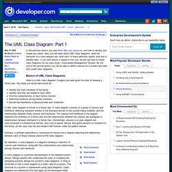
Now, you will learn about UML class diagrams, what the elements of a class diagram are, what each of these elements signify, and how to identify them. In our next article, a sequel to this one, we will see how to create class diagrams for our case study—Courseware Management System. By the end of the second article, you will be able to define classes for a system and read and create class diagrams. Practical UML: A Hands-On Introduction for Developers. The heart of object-oriented problem solving is the construction of a model.
The model abstracts the essential details of the underlying problem from its usually complicated real world. Several modeling tools are wrapped under the heading of the UML™, which stands for Unified Modeling Language™. The purpose of this course is to present important highlights of the UML. At the center of the UML are its nine kinds of modeling diagrams, which we describe here. Some of the sections of this course contain links to pages with more detailed information. Why is UML important? Let's look at this question from the point of view of the construction trade.
Writing software is not unlike constructing a building. The UML is applicable to object-oriented problem solving. Models consist of objects that interact by sending each other messages. UML 2 Class Diagrams: An Agile Introduction. UML 2 class diagrams are the mainstay of object-oriented analysis and design.
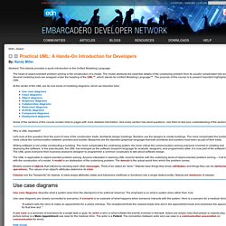
UML 2 class diagrams show the classes of the system, their interrelationships (including inheritance, aggregation, and association), and the operations and attributes of the classes. Class diagrams are used for a wide variety of purposes, including both conceptual/domain modeling and detailed design modeling. Although I prefer to create class diagrams on whiteboards because simple tools are more inclusive most of the diagrams that I'll show in this article are drawn using a software-based drawing tool so you may see the exact notation. In this article I discuss: 1. Figure 1 depicts a start at a simple UML class diagram for the conceptual model for a university. Figure 1. Enrollment is an associative class, also called a link class, which is used to model associations that have methods and attributes.
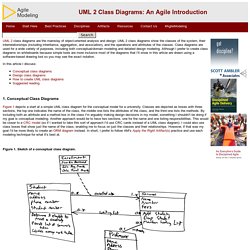
Figure 2 depicts a reworked version of Figure 1, the associative class has been resolved.