Terrain Visualization and Flyby Animation. 3DEM for Win95/98/ME/2000/XP and Windows Vista will produce three dimensional terrain scenes and flyby animations from a wide variety of freely available data sources including: USGS Digital Elevation Model (ASCII DEM) files USGS Spatial Data Transfer Standard (SDTS DEM) files NASA Shuttle Radar Topography Mission (SRTM) files LIDAR Point Cloud (LAS) files USGS Global 30 Arc Second Elevation Data Set (GTOPO30 DEM) files NOAA Global Land One-km Base Elevation (GLOBE DEM) files NASA Mars Orbiter Laser Altimeter (MOLA) files Any topographic data file organized by rows and columns of elevation data XYZ scattered point topographic data files Terrain data files can be saved in the following formats for use by other GIS programs USGS ASCII Digital Elevation Model (*.dem) GeoTiff Graphics File (*.tif) GeoTiff Digital Elevation Model (*.tif) Binary terrain matrix (*.bin) VRML world (*.wrl) Terragen terrain (*.ter) Windows Bitmap (*.bmp) Joint Photograhic Experts Group (*.jpg, *.jpeg)
Creating Contour Maps. Creating Contour MapsCreating 3d contour maps using heightmaps in processing. For some of our past projects we were in the need of creating 3d contour maps in Processing. A contour, or topographic map, uses contour lines which join points of equal elevation above a given level to show valleys and hills. You can think of these lines as intersection of a 3-dimensional surface and several horizontal planes. The following tutorial will cover two main questions. Creating a contour map We started working on different approaches creating the contour maps but realized most of them were either too slow, the results were not really satisfying, or it wasn’t possible to transform them to 3d as they were pixel based.
So after testing different libraries, we decided to use v3gas Blob Detection library which seemed to be the best for our purpose. Processing code import blobDetection. PImage img; void draw() { background(0); translate(-img.width*factor/2,-img.height*factor/2); Creating heightmaps. Working with terrain data. If you've found yourself on this page, we're assuming you've To get good-looking terrain maps, we usually combine several types of visualizations generated by the GDAL DEM utilities. Digital Elevation Model sources There are many different data formats for storing and working with digital elevation models. In our examples we’ll be working with geotiffs. Here are some examples of high quality free datasets that are available in geotiff format: Data collected from NASA’s Shuttle Radar Topography Mission is a high quality source of elevation data covering much of the globe.
It is available free from NASA directly, however we recommend working with CGIAR’s cleaned up version, which is also free. Aster is another global DEM datasource. The US Geological Survey publishes a National Elevation Dataset for the United States. Types of Visualizations Color-relief (or hypsometric tint) Color relief assigns a color to a pixel based on the elevation of that pixel. Hillshade (or shaded relief) Slope. Welcome to the JMARS website | JMARS - Java Mission-planning and Analysis for Remote Sensing. Isis Cube Format - Isis Workshop. From Isis Workshop [edit] What Is A Cube? Illustration of an Isis image cube, showing the three dimensions of an Isis image: width (samples), height (lines), and depth (bands) A cube is a 3-dimensional image with axis: samples, lines, and bands. The physical dimensions of a cube are called the number of samples (NS), number of lines (NL), and number of bands (NB).
Typically, the sample and line dimensions are used to represent spatial information while the band dimension represents spectral information. Image Data Dimensions from Planetary Missions (*) means the number of lines per image is variable [edit] Interactive Cube Demonstration [edit] What Are Pixels? Counting Pixels: Lines and Samples The individual cells within a cube are called pixels. Move your mouse cursor over the cube (right) and pay attention to the sample/line positions of each pixel shown below the cube: Did you notice that sample 1 is on the left edge of the image and line 1 is on the top edge.
[edit] Bit Type Basics. UW MOLA DEM downloads. All of the planet from 60 degrees S to 60 N has been processed, but a third of all tiles failed visual inspection because uncalibrated points found their way into the input stream. We could manually pick more orbits to expand the badorbits and verybadorbits lists, but we are distracted by more elaborate schemes to filter the input points. All of the approved tiles are ready for downloading. The first data available will be a combination of version 1.0 and version 1.02 processing. The difference involves the algorithm by which suspect points are restored to consideration if they are far from more reliable points.
Versions 1.03 and 1.04 are essentially the same, but they check for a local verybadorbits and badorbits list. The arrival of HiRISE DEMs interests us. Pds-geosciences.wustl.edu - /mgs/mgs-m-mola-5-megdr-l3-v1/mgsl_300x/meg128/ Pds-geosciences.wustl.edu - /mgs/ PDS Geosciences Node Data and Services: MGS MOLA MEGDRs. Mars Global Surveyor: MOLA MEGDRs April 19, 2007. New polar planetary radius maps now accompany the polar topography maps in this data set.
Mission Experiment Gridded Data Records The MOLA Mission Experiment Gridded Data Records (MEGDRs) are global topographic maps of Mars created by binning altimetry values from the MOLA PEDR products acquired over the entire MGS mission. MEGDRs have been produced at resolutions of 4, 16, 32, 64, and 128 pixels per degree. The final version of the MEGDRs was released May 7, 2003. A MEGDR product consists of a set of three or four maps: The planetary radius as recorded by the MOLA instrument The areoid, a model for an equipotential surface of Mars, analogous to "sea level" on Earth (this map is omitted for the 32, 64 and 128 pixel/degree and polar MEGDRs) The topography computed as the difference between the planetary radius and the areoid Counts (number of observations) per cell in the map MEGDR Data Online Online Tools C = 4 pix/deg E = 16 pix/deg.
Spec doc. Geomorphometry_2008.pdf. MOLA Experiment Gridded Data Record. This is the format used for, amoung other things, the topographic grid data for the mars terrain databases. The files are plain ASCII with 6 columns as follows. Longitude Latitude Average observed radius Areoid radius Median observed topography Number of observations Example More details can be found on the NASA sites, in particular, further details on the mars datasets is given below. Quote The MOLA IEGDR is in the form of an ASCII table with one row for each latitude-longitude bin, from 90 to -90 degrees latitude and from 0 to 360 degrees longitude. The binned data include all MOLA nadir observations from the Orbit Insertion phase, plus Mapping Phase nadir observations, plus off-nadir observations of the north pole above 86 degrees latitude acquired during spring 1998 and of both poles taken in July 1999.
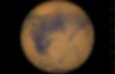
Orbits 355 and 358 of the Orbit Insertion Phase and orbits 10709 through 10716, inclusive, of the Mapping Phase are excluded because solutions for these orbits are deemed to be poor. File Formats used by LandSerf 2. Mars Global Data Sets. Topography of the Martian Surface.