
RS485 Serial controlled Eight Channel Relay Board - 12V. Home :: DIN mount rail :: RS485 8 Channel Relay Controller, 12V, with clips for DIN mount rail Features: The board is fully compatible with the old version.This new version has an option to change the ID (from ID 01 to ID 15) manually through a DIP Switch placed near RS485 connector.

Dimensions:108 mm / 150 mm/ 25mm (connectors mounted) USB/RS232 Relay Controller - 4 Relays - Relais - Interfacing - Modules. MOD-IO. RLY08 I2C Mode. RLY08 - 8 Relay Outputs Technical Documentation I2C modeFor serial mode click here Connections I2C Mode selection I2C operation is activated when the mode pin is left open circuit.
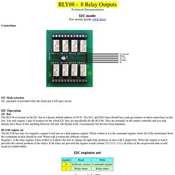
I2C OperationI2C BusThe RLY08 is located on the I2C bus at a factory default address of 0X70. The SCL and SDA lines should have pull-up resistors on them somewhere on the bus. RLY08 register setThe RLY08 has only two registers, register 0 and acts as a dual purpose register. I2C register set Commands for I2C Changing the RLY08 Address To change the I2C address of the RLY08 you must have only one module on the bus. Take care not to set more than one module to the same address, there will be a bus collision and very unpredictable results. UART Serial controlled Eight Channel Relay Board - 12V. USB Eight Channel Relay Controller - RS232 Serial controlled - 12V. RS485 Serial controlled Eight Channel Relay Board - 12V. RS485 Serial controlled Eight Channel Relay Board - 12V. Relay Plug - Hardware. The Relay Plug is a small board containing two miniature relays for switching AC and DC loads.
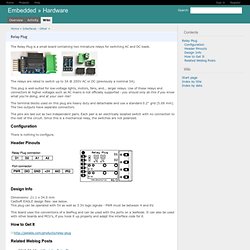
The relays are rated to switch up to 3A @ 250V AC or DC (previously a nominal 5A). This plug is well-suited for low-voltage lights, motors, fans, and... larger relays. Use of these relays and connectors at higher voltages such as AC mains is not officially supported - you should only do this if you know what you're doing, and at your own risk! The terminal blocks used on this plug are heavy duty and detachable and use a standard 0.2" grid (5.08 mm).
The two outputs have separate connectors. The pins are laid out as two independent pairs. Configuration¶ Tutorial Module-Rail-Relay - GNUBLIN. The GNUBLIN Module-Rail-Relay is an extension board for the Gnublin and provides 4 relay contacts.
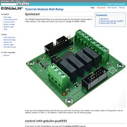
The relays can switch up to 5A at a voltage of 250VAC/30VDC. If you use the standard Gnublin Distribution you just have to connect the module via a ribbon cable to the gnublin. MOD-IO2. MOD-IO (Relay IO Module I2C) RLY08 I2C Mode. I2C Bus Open Collector, PCF8574A [EI2C-9AHA] : ERE, Electronics Store,Embedded,Modbus,I2C boards. I2C Bus High Current Relay , 12v, PCF8574A [I2C-RL812MA] : ERE, Electronics Store,Embedded,Modbus,I2C boards. Description: This is an I2C relay board.
![I2C Bus High Current Relay , 12v, PCF8574A [I2C-RL812MA] : ERE, Electronics Store,Embedded,Modbus,I2C boards](http://cdn.pearltrees.com/s/pic/th/pcf8574a-electronics-embedded-78970241)
The board for remote 8 relays expander for i2c bus based on PCF8574A. Making it ideal as relay outputs expander for i2c bus. It is designed to compatible with most microcontrollers. The board supports 100khz, i2c bus frequency. Address by 3 jumpers for use of up to 8 boards or 64 relays. An operating logic supply voltage is 2.5-5.5v with inverse polarity protection. PCB size fits on DIN-rail PCB holder, 72x87.5mm. This package does not include DIN-rail PCB holder. Features: Documents:manual, schematic, bom, pcf8574 datasheet Applications:Arduino example If your browser program can't show pdf files on display completely, please save it into your computer and open it by pdf reader program.
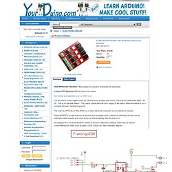
4 Opto-Isolated Power FET Switches (Improved Version) NEW IMPROVED VERSION: Now easier to connect: terminals for each load. 4 Power FET Switches (IRF540 type) Free cables See Details and Applications on our WIKI here: Can be used to control higher power DC devices such as lights and motors.
Opto-Isolated 2 Channel Relay Board (Price reduced again) Opto-Isolated 2 Channel Relay Board See more details, applications on our WIKI here: With high-current relays, AC250V 10A ; DC30V 10A NOTE: Each relay draws about .08A (80ma) so about 4 relays are the maximum you should run from the Arduino +5V supply.
(Running from USB it may be less). More than 2 relays: we recommend you use a separate 5V supply for the relays. Dimensions here: NOTES: If you want complete optical isolation, connect "Vcc" to Arduino +5 volts but do NOT connect Arduino Ground. If relay isolation is enough for your application, connect Arduino +5 and Gnd, and leave Vcc to JD-Vcc jumper in place. NOTE: It is sometimes possible to use these relay boards with 3.3V signals, IF the JD-VCC(RelayPower) is provided from a +5V supply and the VCC to JD-VCC jumper is removed. . NOTE: The digital inputs from Arduino are Active LOW: The relay actuates and an LED lights whe the input pin is LOW, and turns off on HIGH. $5.66 4-Channel AC/DC Relay Module - 125V-250V AC / 30V DC / 10A per channel at FastTech. Ol Components MOSFET Power Control Kit. Xbee Relay Shield. Description: The Relay Shield is an Arduino compatible smart module with 4 mechanical relays providing an easy way to control high voltage.

The max switching power is 35VDC 70W for each channel. It can be directly controlled by Arduino through digital IOs with external 9V DC supply. With the XBee form socket and 315/433MHz RF module interface, the Relay shield can be remotely controlled, making it easy to use in robotics, industry control, smart houses etc. Note: Take care the pins on the Shield should not be touched with USB connector of Arduino UNO when they are connected . Wifi and zigbee series products : wifi relay remote control board. WiFi232-RELAY8 remote controller , Eight channel relay output Product Features: 1.
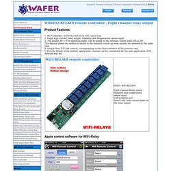
Wi-Fi interface, network control via wifi connection 2. Eight high-current relay output, Humidity and Temperature sensor input 3. The unique AP + STA operating mode, can be added to the ordinary router itself still as AP.