
20 Arduino projects of 2012 | Nudatech While looking for ideas for new some new project I noticed there aren’t many lists of Arduino projects online so I decided to make one and in the last few days I’ve been carefully digging Reddit (r/Arduino) and the Arduino forum until I ended up with a list of 20 Arduino projects. All the projects in this list follow two simple criteria: They’ve been published/released in 2012.They provide quite detailed info (the more the better). The second criteria forced me to discard some amazing projects, but I didn’t want this post to be a simple showcase of cool Arduino projects, I wanted it to be an useful reference for Arduino users. 20. arduino-l3dgecomm This project aims to integrate a 3D world with real sensors and motors, more a proof of concept than a proper project, but still an interesting idea. 19. A custom PCB designed in the shape of a Christmas tree, an Atmel ATTiny45 microcontroller, 5 IO pins, and 20 LEDs make a perfect Christmas ornament. 18. 17. 16. 15. 14. 13. 12. 11. 10. 9. 8. 7.
RFLink Wiring Details ⋅ Easy Home Automation RFLink Wiring Details 01 July 2015 Using a seperate RF receiver and RF transmitter: Prefferred are Aurel RF receivers. If building this yourself is too complicated or you dont have the time, then you can also buy a ready made RFLink board / RFLink Shield at the Nodo webshop Receivers and Transmitters: Various receivers/transmitters/transceivers have been tested. If you would like to use the Aurel RTX MID 5v Transceiver the pinout is: Pin 1 = Antenna Pin 2 = Ground Pin 3 = Not Connected Pin 4 = MEGA tx3/Pin 14 (TX Data) Pin 5 = MEGA rx3/Pin 15 (TX Enable) Pin 6 = MEGA Pin 22 (-RX/TX- toggle signal!) If you would like to use the RXB6 receiver the pinout is: RXB6: Pin 1 = Antenna Pin 2 = Not Connected / Ground Pin 3 = Not Connected / Ground Pin 4 = Not Connected Pin 5 = MEGA tx2/Pin 16 (RX VCC) Pin 6 = Not Connected Pin 7 = MEGA rx1/Pin 19 (RX Data) Pin 8 = Ground The above diagram also has some interesting improvements courtesy of Snips. IMPORTANT NOTE about the well-known cheap Chinese set:
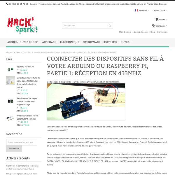
Wireless power outlets for home automation using Arduino Home automation becomes more and more popular, affordable and fascinates people. Internet offers such possibilities as never before. Impress your friends showing on Iphone that you can switch on/off lamp in your apartment 1000 km away and simultaneously see it through a webcam. Wirelessly controlled power outlets are best suited for switching on/off appliances as they do not need cables and only the remote control needs to be interfaced to a microcontroller. Picture below illustrates how home automation box could look. The first attached pdf file contains details how to program Arduino for steering the wireless power sockets. Second pdf file describes how to connect sensors and relays.
AVR Tutorial - AVRDUDE OK now you have a target board and a programmer next you will use the software you installed in step 2 to talk to the chip. This software is very powerful but its also difficult to use the first time. However, you should persevere and after a few times it will become (easier) to use. Comments? Avrdude is a command line program, so you'll have to type in all the commands (later you'll find out how to shortcut this with a Makefile) Under Windows, you'll need to open up a command window, select Run... from the Start Menu and type in cmd and hit OK. Under MacOS X, you can use the Terminal program to pull up a command line interface, its in the Utilities folder Now in the new terminal window type in avrdude you should get this response, which is basically a simple list of what avrdude can do... There are a lot of options, lets review them quickly. : This is just to tell it what microcontroller its programming. The ones you'll use 99% of the time are highlighted in red. C:\>avrdude -c asdf
Android et arduino De Wikidebrouillard. Article incomplet en cours de rédaction Présentation de l'expérience Vous venez de réaliser les tutoriels d'arduino, et vous etes à la recherche d'un nouveau "truc" à faire avec cette petite carte. Dans cette page, nous vous proposons de connecter votre arduino à un téléphone android. Matériel un arduino un smartphone sous android et avec l'option bluetooth - avoir activé "sources inconnues" dans les parametres un grove shield (pas indispensable) une carte bluetooth (indispensable) un ordinateur connecté à internet L'expérience La manipulation Tout d'abord ici l'idée n'est pas d'apprendre à programmer Arduino mais de comprendre comment interfacer celui-ci avec un téléphone sous Android. I préparation de l'Arduino : Donc dans un premier temps, chargez le programme ci-dessous dans votre arduino. Une fois le programme uploadé connectez le module bluetooth et la led comme ci-dessous : II App Inventor 2. rendez vous à cette adresse : Que voit-on ?
Suivre sa consommation d’eau : domotisation d’un compteur d’eau à l’aide d’un arduino | Connecting Stuff Bonne année à tous (mieux vaut tard que jamais :). Pour commencer cette année, un petit article sur le relevé automatique de la consommation d’eau. Le montage utilise un compteur d’eau banal du commerce (sans capteur donc) et ne nécessite pas son démontage. [adsGrandRectangleTexte] Relever sa consommation d’eau : les différentes solutions Pour faire du relevé de compteurs d’eau, il n’y a pas 36 solutions. Les solutions commerciales, « plug&play », fiables … et pas trop bon marché Il existe des compteurs avec une sortie pour un capteur à impulsion? On le trouve chez planète domotique par exemple : La solution du pauvre, play&plug ;), aussi fiables et pas chères ! Comme d’habitude je suis parti sur une solution la moins chère possible et sans sacrifier la fiabilité. Domotisons un compteur d’eau classique Là aussi, il existe plusieurs solutions. Fonctionnement du CNY70 :
Assembly Instructions | ArduCopter Table of Contents Assembly Instructions The first step in setting up your copter is to assemble the frame and wire the components. These instructions will provide guidance for assembling and wiring your copter with APM autopilot, including best practices. The following subpages provide detailed instructions for these topics: Assemble frame 3DR APM:Copter kits are available from store.3Drobotics.com. 3DR Quad 3DR Hexa 3DR Hexa-to-Y6 Conversion 3DR Y6 Wiring The diagram below shows a standard wiring example for APM:Copter. A complete APM:Copter requires the following electronic components: Autopilot: APM:Copter currently supports APM and PX4 autopilots.Power module with LiPo battery or equivalent powering method (see below)Power distribution board (PDB) or equivalent method of allocating power to the motorsElectronic speed controller (ESC) for each motorMotorsRC receiver and transmitter Powering your copter Connect ESCs and motors Best practices Warning! Questions about this page?
Secret Arduino Voltmeter – Measure Battery Voltage A little known feature of Arduinos and many other AVR chips is the ability to measure the internal 1.1 volt reference. This feature can be exploited to improve the accuracy of the Arduino function – analogRead() when using the default analog reference. It can also be used to measure the Vcc supplied to the AVR chip, which provides a means of monitoring battery voltage without using a precious analog pin to do so. I first learned of this technique from these articles – Making accurate ADC readings on the Arduino, and Secret Voltmeter. In this article, I have incorporated some additional improvements. Motivation There are at least two reasons to measure the voltage supplied to our Arduino (Vcc). A common assumption when using analogRead() is that the analog reference voltage is 5.0 volts, when in reality it may be quite different. double Vcc = 5.0; // not necessarily true int value = analogRead(0); double volt = (value / 1023.0) * Vcc; // only correct if Vcc = 5.0 volts How-To Usage where
CopterControl Platform - OpenPilot.org - The Next Generation Open Source UAV Autopilot The CopterControl & CC3D boards are an all-in-one stabilization hardware which runs the OpenPilot firmware. It can fly any airframe from fixed wing to an octocopter and is configured and monitored using the OpenPilot Ground Control Station (GCS) software. The retail CC3D board comes with everything pictured above, 3D printable cases are available for extra physical protection. In 2012 the Original CopterControl boards were discontinued due to lack of available gyro sensors, The board was slightly revised and released with a new gyro sensor that is less effected by temperature changes. The new revision is called CC3D, other than the single sensor it is identical to the original CopterControl. Both CopterControl & CC3D boards are 100% compatible when updated to the v3 bootloader. The CopterControl hardware has the following features: Flexiport CopterControl also offers the innovative Flexi-port which provides either I2C connectivity or a second serial port.