PaperDimmerPCB. Regulador de potencia por triac para microcontrolador (compatible con Arduino)
Conceptos preliminares Después de buscar un regulador de potencia para microcontrolador mediante triac, sólo he encontrado controles binarios (encendido/apagado), o mediante circuitos especializados. Es por eso que decidí hacer un control sencillo (sólo tiene 8 niveles de potencia). El circuito se basa en el expuesto en la web (muy buena por cierto). En este circuito sustituimos el potenciómetro de 470k por 3 resistencias fijas en serie que puentearemos según nos convenga. Esto lo hacemos mediante tres optoacopladores que a la vez de aislar la parte del micro de la parte de potencia, puentean las resistencias que están situadas en paralelo con el " foto interruptor bidireccional". NOTA: Este circuito funciona solo con motores de tipo universal (con escobillas), para regular la velocidad de motores de inducción (sin escobillas) es necesario realizar un variador de frecuencia. Características del circuito Descripción Y por el lado de las pistas: 1.
Cables
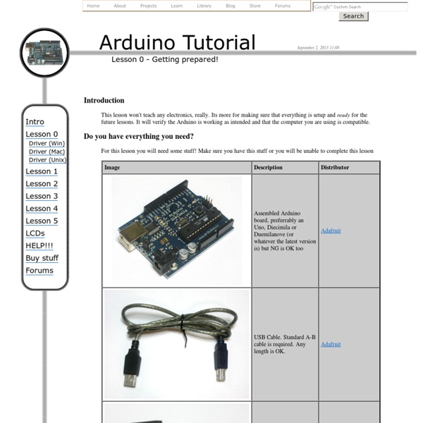
Arduino is great but sometimes connecting interesting things to it can be a pain. Here are some things that may make it easier for you. Here are some of the cables and pins that are available, and below we'll show you how to use them for many different applications. Here are a few places you can jump to, if you're in a hurry: For use on Breadboards many people use "jumper wires" with male pins on both ends. Many Input and Output devices (and servos, which this pinout is based on) have one signal pin plus Vcc(Usually +5V) and Ground. Here's an example of how easy it is to connect an input device (Switch) and an output device (LED) using this cable. Sometimes you need to connect to some device that is not an Electronic Brick. On the right is the YourDuinoRobo1 Arduino-compatible board. There is also a very useful cable that plugs into a Sensor Shield on one end, but has separate female sockets on the other end. You will also see three red individual wires in the photo (right).
Resultados de la búsqueda de arduino
Prmero tenemos Centipede un shield bastante bien diseñado que nos da 64 pines de entrada o salida, todo esto gracias al protocolo I2C. Tiene un precio de $17.99 USD y puedes comprarlos aquí. Otro multiplexor para arduino es el Mux shield, tiene capacidad hasta 48 entradas o salidas. Este shield hace uso de multiplexores analogicos lo cual hace posible tener hasta 48 entradas analogicas, una cualidad única. El EZ-Exparder Shield, el más sencillo pero tambien más económico, con una expansión de tan solo 13 pones extra que además solo funcionan como salida y que tienen una corriente de salida limitada.
Introduction to using openFrameworks with Arduino
Introduction to using openFrameworks with Arduino Skill Level: Intermediate by CTaylor | January 26, 2012 | 1 comment What is openFrameworks? openFrameworks is a very handy software library written in C++ that is written for the sole purpose of reducing the software development overhead faced by designers and artists that would like to create pieces that use various media (graphics, sound, video, electronics, etc.). For some great examples of projects that use Arduino and the oF libraries, be sure to check out the openFrameworks section of the Arduino Blog. Very impressive fluid dress concept by Charlie Bucket What will we do in this tutorial? This tutorial will go step-by-step through the process of installing openFrameworks, getting programs running with it and then using the oF software libraries to communicate over USB with an Arduino UNO. This tutorial assumes that: You know the programming and basic use of Arduino. Step 1: Install openFrameworks and Code::Blocks Now install Code::Blocks ...
Talleres Arduino | Andres Duarte Marin
Duración: 12 horas Próxima edición*: 5, 6, 12 y 13 de octubre de 2013 Horario*: S, D 16:00 – 19:00 Precio: 80 € Número de plazas: 15 Tipo de sesión: sesión teórico-práctica. Los días 5, 6, 12 y 13 de octubre de 2013 de 2013 en INTERVENTO RED MADRID. Duración: 3h Próxima edición*: 13 de julio de 2013 Horario*: S 16:00 – 19:00 Precio: 20 € Número de plazas: 15 Tipo de sesión: sesión teórico-práctica. Duración: 3h Próxima edición*: 29 de junio de 2013 Horario*: S 16:00 – 19:00 Precio: 20 € Número de plazas: 15 Tipo de sesión: sesión teórico-práctica. LOS DÍAS 25 y 26 DE MAYO, Y 1 Y 2 DE JUNIO DE 2013 EN INTERVENTO RED MADRID. Este taller muestra cómo programar y diseñar circuitos para conectar diversos dispositivos. Duración: 30h Próxima edición: 25 y 26 de mayo, y 1 y 2 de junio de 2013 Horario: S, D 16:00 – 19:00 Precio: 80 € Número de plazas: 15 Tipo de sesión: sesión teórico-práctica Lugar: INTERVENTO: Calle de Fernando Poo, 4 28045 Madrid Profesor: Andrés Felipe Duarte Marín Contenidos Donde?
Blog » OpenFrameworks
Makers need to familiarize themselves with the core concepts and the theory involved in creating applications such as Motion Sensing and Face Tracking. As the technology is churning out new hardware day and night, DIYers need to work hard to keep up and always be in touch with the latest technology around them. For example, anyone working with Accelerometers/ Gyroscopes or Inertial Measurement Units needs to understand the theory of Vectors, Force, Gravity and be able to work out complex mathematical problems. They may easily get an Arduino Board and an Accelerometer Breakout or an IMU Board and use a library instead of writing their own code but to truly understand the theory behind it; how the device actually works, is not for the faint of heart. One such problem is the Face Tracking Application. Unless you know the real theory behind how the Algorithm actually works, you can only wonder about that robot which follows its master. In an introductory post, Greg writes:
How to drive drive brushless motor with Arduino?
Arduino motor control