Adafruit's Raspberry Pi Lesson 4. GPIO Setup
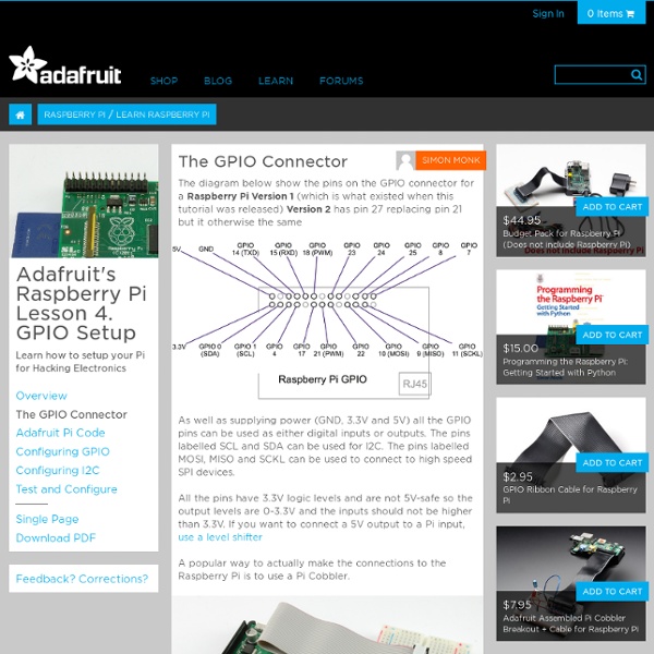
The diagram below show the pins on the GPIO connector for a Raspberry Pi Version 1 (which is what existed when this tutorial was released) Version 2 has pin 27 replacing pin 21 but it otherwise the same As well as supplying power (GND, 3.3V and 5V) all the GPIO pins can be used as either digital inputs or outputs. The pins labelled SCL and SDA can be used for I2C. All the pins have 3.3V logic levels and are not 5V-safe so the output levels are 0-3.3V and the inputs should not be higher than 3.3V. A popular way to actually make the connections to the Raspberry Pi is to use a Pi Cobbler. Make extra extra double-check sure that the PIN 1 indicator is in the corner of the Pi. This uses a ribbon cable to connect the GPIO connector to solderless breadboard, where you can add your own components.
Pins | Wiring Pi
Pin numbering of the BCM2835 GPIO port(s) on the Raspberry Pi has been a source of great confusion since the designs for the Pi were first published. In the early days (even before hardware was available) the default usable GPIO pins were simply referred to by number as GPIO0 through GPIO7. Additionally there were pins for other purposes, SPI, I2C and serial. So when initially writing wiringPi, I chose to have the same default pin numbering scheme and numbered them from 0 upwards. However this has subsequently been viewed as “wrong” and several people have expressed concern about my numbering scheme, however I’ve stuck with it (as by then people were using wiringPi). and it’s proven its worth over the hardware board revisions where some pins changed their hardware definitions, however wiringPi was able to hide this from the user. The P5 connector is designed to have the header soldered on the underside of the board. For a printable version of these tables, click here.
Raspberry Pi | Wiring | Pins
Update: 14th May, 2013 wiringPi version 2 has been released and now has its own website ( to look after it. Most of the documentation on the projects site has been copied over to it the new site, but there may still be 1 or 2 pages that are still missing. I’d encourage you to use the new site if possible where there will be a forum and wiki. The following tables give the mapping of the Raspberry Pi GPIO Pins to the GPIO connector in relation to the pin numbers and the physical location on the connector. If using the connector pin numbering, then note that Pin 1 on the connector is the 3.3v supply. P1: The Main GPIO connector: Board Revisions: Please note the differences between board revisions 1 and 2 (R1 and R2 above) P5: The auxilliary GPIO connector present on Rev. 2 boards only: Note also that the P5 connector is designed to be used from the underside of the Pi – ie. you solder on the top of the Pi board to install the connector! Each side has three columns.
DomoRasPi
Related:
Related: