
Raspberry Pi Un article de Wikipédia, l'encyclopédie libre. Le Raspberry Pi est un nano-ordinateur monocarte à processeur ARM conçu par le créateur de jeux vidéo David Braben, dans le cadre de sa fondation Raspberry Pi[2]. Cet ordinateur, qui a la taille d'une carte de crédit, est destiné à encourager l'apprentissage de la programmation informatique[2] ; il permet l'exécution de plusieurs variantes du système d'exploitation libre GNU/Linux et des logiciels compatibles. Son prix de vente était estimé à 25 $, soit 19,09 €, début mai 2011. Historique[modifier | modifier le code] Conception[modifier | modifier le code] Version alpha de la carte. En 2006, les premiers prototypes du Raspberry Pi sont développés sur des microcontrôleurs Atmel ATmega 644. L'objectif de la fondation est alors de proposer deux versions, l'une à 25 $ US et une deuxième à 35 $ US. Prototype[modifier | modifier le code] En octobre 2011, une version de RISC OS 5 tournant sur la carte est présentée. Différences avec le A[59] :
Arduino RGB LED Color Wand Here is an artistic Arduino project for the fun-minded. The circuit is an Arduino RGB LED controller running on a sweet ‘n’ simple code,but with a little hardware surprise outside the Arduino board. You can add a bit of luxury to your aquarium or flower vase using this digital color wand! Here, D11-D10-D9 pins of Arduino is used to drive the Red, Green, Blue Anodes of the common-cathode RGB LED (L1) through independent 270 Ohm current limiting resistors (R1-R3). At first glance, you may think such a powerful mosfet is superfluous here, but the selection is intentional. Arduino Sketch Code As said above, the mosfet mechanism allows easy circuit tinkering. Note: RGB LEDs are actually just 3 LEDs (red, green, blue) that share one lens, and have one of their 2 pins in common.
MaKey MaKey Quickstart Guide Introduction Welcome to the world of Makey Makey! A world where everyday objects are much more than they appear. Bananas are more than just a curvy fruit --- they're keys to a virtual piano. Play-Doh isn't just a child's toy --- it's the controlling force behind Pacman's up/down/left/right. And your simple pencil drawings are a portal to Portal. Be prepared to look at everyday objects in a whole new light. Materials Required Makey Makey --- The star of the show! Suggested Reading What is a Circuit? Every electrical project starts with a circuit. What is the Makey Makey? The Makey Makey is a collaborative project between Jay Silver and Eric Rosenbaum of the MIT Media Lab and SparkFun Electronics. Hardware Overview Top Side The Makey Makey is a two-sided circuit board. Each of those inputs as well as the very important “Earth bar” are available in the form of what I like to call “alligator-bait” connectors. Back Side You've also got access to 12 more keys via the black female headers: Warning!
Utiliser votre Arduino comme voltmètre Pour un projet utilisant des batteries lithium, j’ai besoin de savoir lorsque mes batteries sont chargées à moins de 4V. Mon projet étant sous Arduino Uno je me suis demandé s’il était possible d’utiliser l’équation de diviseur de tension pour me servir de mon Arduino comme d’un voltmètre. L’équation de diviseur de tension consiste en un circuit composé de deux résistances qui change une tension élevée (Vin) en une tension plus petite (Vout). Voilà comment cela se traduit en schéma électronique: Pour réaliser mon voltmètre avec mon Arduino Uno, j’ai réutilisé l’afficheur LCD branché sur 3 pins. Sur le schéma on voit que j’utilise: 5 résistances de 10K ohms en série (R1)2 résistances de 2.2K ohms en série (R2) R1 et R2 me permettent de tester des tensions pouvant atteindre 50Volts puisque si l’on applique la formule du diviseur de tension, une tension de 50V en entrée me donnera 4V en sortie. Pour calculer vos résistances R1 et R2, je vous conseille d’utiliser ce calculateur.
Curriculum | 3Doodler EDU At 3Doodler, we are committed to supporting educators with curricular materials that inspire and make it easy to create. The materials hosted on this page are designed to introduce the 3Doodler into classrooms, libraries, museums, and makerspaces. All materials are freely available and downloadable. Educators should feel free to adapt, hack or modify the suggested activities, lesson plans and units to meet their needs and those of their students. 3Doodler Classroom Basics Prepare your students for more advanced lessons using the 3Doodler while inspiring and engaging them at the same time! Forward, Doodle, ReverseDownload From Two Dimensions to ThreeDownload Exploring MaterialsDownload Bridge Engineering & Design: A STEM Introduction with 3Doodler A STEM Introduction with 3DoodlerDownload Bridge Engineering & DesignDownload Principles of Art & Design Line, Shape, FormDownload Computational Thinking with the 3Doodler A Digital Schoolhouse WorkshopDownload
Makey Makey ? Go ! Faut-il encore présenter la Makey Makey, cette carte qui permet de transformer tout matériau et object pouvant conduire l'électricité en bouton interactif ? Celle-ci revient dans une version simplifiée mais pas inintéressante, le Makey Makey Go. La Makey Makey Go se présente comme une clé usb et diffère fortement de la Makey Makey telle que vous la connaissez. Ses fonctions en sont particulièrement réduites et il s'agit plus d'un gadget que vous pourrez avoir facilement dans votre poche ou accroché à votre porte clés permettant, tel un clown MacGyver des temps modernes, d'impressionner et d'amuser les foules en un rien de temps. La Makey Makey Go comporte trois boutons. Le premier n'est autre qu'un connecteur qui, au choix, simulera la touche espace ou le clic gauche de la souris (signalés par une led de couleur différente), choix effectué en appuyant sur le troisième bouton. J'avoue être loin d'avoir exploré les nombreuses possibilités de la Makey Makey Go.
Arduino Ce projet va vous permettre de réaliser un oscilloscope minimaliste et d'expérimenter la communication série avec un autre logiciel que celui d'Arduino, en l'occurrence, Processing. Un oscilloscope permet de visualiser les variations d'une tension dans le temps, sous forme d'une courbe. Le principe de fonctionnement de ce projet est le suivant : L'Arduino mesure une tension sur une entrée analogique. Précautions L'oscilloscope ainsi réalisé ne sera capable de mesurer que des tensions comprises entre 0 et 5 V. Éléments nécessaires Montage électronique Comme expliqué ci-dessus, le montage se résume à deux fils connectés à l'Arduino, qui vont servir à mesurer un autre montage soumis à une tension variable. Première étape Copiez le programme suivant dans Arduino. /* Ce programme consiste simplement à mesurer l'entrée analogique 0, et à transmettre le résultat via une communication série. Deuxième étape Après avoir téléchargé et installé Processing, copiez le programme suivant dans Processing.
Projects from Tech: Simple Arduino Robot Arm from 9 gram servos Greetings once again. I just wanted to take the opportunity to introduce you to my new robot arm. It doesn't have a name, but it is made from house insulation foam and 9 gram servos. I won't do a full tutorial on this because frankly it isn't required. There are tons of this sort of thing out there. Use mine as a starting point for your own design based on what you have sitting around. For this project you will need a few things. The first is an Arduino or other microcontroller. Next you will need two HXT900 9gram servos (or similar). For the arm's physical construction I will be using half inch house insulation foam. Last you will need some sort of hinge bracket. First, cut two lengths of foam about 6.5" x 1". Next we are going to glue it together. Next we are going to make the other arm segment. Next I screwed a screw into the center of the arm about a half inch from the end. Next we need to mount the elbow servo in the 1st arm segment. Go ahead and cut a base.
Perroquet buzzer De Wikidebrouillard. Article incomplet en cours de rédaction Présentation de l'expérience Nous allons réaliser un système qui permet d'enregistrer et répéter des séries d'impacts reçues par un objet, tel un perroquet qui répète ce qu'il entend. Matériel L'expérience La réalisation Réaliser le montage suivant : Lancer le logiciel arduino. Relier l'arduino au pc. Que constate-t-on ? Après une série de sons perçus par l'objet, on attend que la LED s’éteigne, puis on entend une répétition de la série de sons produits précédemment. Explications De manière simple Le programme enregistre la série de sons reçus, puis après un temps d'attente sans bruit, il envoie un signal à l'enceinte qui le restituera. La LED est allumée tant que l'on peut enregistrer, et est éteinte lorsque la carte lit la série de sons. Après chaque son reçu, il faut un temps avant de pouvoir recevoir un autre son, on appelle cela l'antirebond. Allons plus loin dans l'explication Liens avec d'autres expériences Catégorie Arduino
Alternative Arduino Interfaces Overviewing the Options Arduino is awesome! It’s our go-to electronics education platform, and it’s our top choice for rapid prototyping, but it isn’t for everyone. The Arduino alternatives covered in this tutorial range from simple, introductory graphical programming to web-based Arduino interfaces for your web browser. ArduBlock – A Visual Programming Arduino Extension ArduBlock is a graphical programming add-on to the default Arduino IDE. ArduBlock is a perfect interface if you’re just getting into programming, electronics, or Arduino. Minibloq – Visual Programming Standalone Software In the same vein as ArduBlock, Minibloq is a graphical programming environment where groups of blocks are stacked on top of each other to create your program. One of Minibloq’s most powerful features is its real-time code generation – as you drag blocks into your program, the equivalent code is generated concurrently. Check out the Minibloq section of this tutorial for an introduction to the interface.
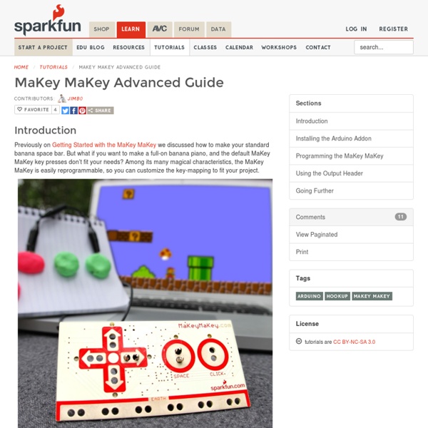
MaKey MaKey Advanced Guide Introduction Previously on Getting Started with the MaKey MaKey we discussed how to make your standard banana space bar. But what if you want to make a full-on banana piano, and the default MaKey MaKey key presses don’t fit your needs? In this tutorial we’ll show you how to use Arduino – the most popular embedded development environment out there – to reprogram the MaKey MaKey and modify which inputs press which keyboard or mouse control. Suggested Reading Before following along with this tutorial, we highly recommend you read through our Getting Started with the MaKey MaKey tutorial. Beyond that tutorial, here are some related tutorials we’d recommend reading as well: What is an Arduino? Installing the Arduino Addon Before you can program the MaKey MaKey using Arduino, you need to download and install the Arduino IDE (integrated development environment). Adding the Addon The MaKey MaKey addon for Arduino adds an entry to the Arduino “Boards” list tailored to the MaKey MaKey. Going Further