
StereoPhoto Maker (French) English , German , Japanese StereoPhoto Maker (SPM) est un éditeur d'images stéréo très souple et performant mais aussi un outil pour visionner les images stéréo. Il permet aussi aux utilisateurs ayant quelques notions de HTML de créer des pages Web utilisant la 'StereoPhotoViewer Applet'. Il faut simplement télécharger le contenu du projet-applet sur le Serveur Web en utilisant un logiciel FTP (il existe des logiciels gratuits de ce type). Téléchargement :StereoPhoto Maker Ver5.00b 1296 Ko 08/Apr/2014StereoPhoto Maker 64bit Ver5.00b Beta 1960 Ko 08/Apr/2014 Ver. 4.43->4.50See here Ver. 4.41->4.43See here English Online Help Great thanks to Pierre MEINDRE for the French-language documentation. Exemples :Exemples d'images stéréo 1Exemples d'images stéréo 2Exemple d'anaglyphe en jaillissement La plupart des modes de visualisation stéréoscopiques sont supportés ainsi qu'un mode monoscopique : Winx3D n'est plus disponible sur le site web original. Options de lancement Visualisation des images
Modeling the Mirascope Using Dynamic Technology - 5. Conclusion Author(s): Lingguo Bu (Southern Illinois University Carbondale) The mirascope provides a worthwhile task to engage prospective and inservice mathematics teachers in the exploration of an appealing physical phenomenon and the development of genuine problem solving skills in STEM-oriented classes. In the beginning, little was clear about the mathematical mechanism underlying the mirage effect of a popular toy. We did not even know how to get started or how to manage the complexity. Acknowledgements The author would like to thank the two anonymous reviewers and the journal editors for their encouragments and constructive recommendations regarding an earlier version of the article. References Brown, S. About the Author Lingguo Bu is an assistant professor of Mathematics Education in the Department of Curriculum and Instruction at Southern Illinois University Carbondale. Lingguo Bu (Southern Illinois University Carbondale), "Modeling the Mirascope Using Dynamic Technology - 5.
Mirascope Meilleures Images en 3D sans lunettes avec la Stéréoscopie La nouvelle tendance de 2010 c’est que tout doit être en 3D… ça tout le monde le sait, alors les cinéastes et tous les autres travaillent sur pleins de technique pour que ce soit le plus réel possible et le tout bien sur sans lunettes (des lunettes 3D bien sûr, pas n´importe quelle paires de lunettes standards)… J’ai surfé un peu sur la toile pour voir ce qu’il se faisait et je suis tombé sur la Stéréoscopie. Définition de la Stéréoscopie (Images en 3D sans lunettes) C’est la capacité de créer avec toutes les techniques possible l’illusion de la 3D dans une image. Cela a été inventé par Sir Charles Wheatstone in 1840. Donc ça date pas d’hier… C’est d’ailleurs le même principe qui est utilisé dans les Stéréogrammes (image ou on voit rien au début puis l’image sort quand on louche) Globalement comment cela fonctionne dans les images ci dessous ? Et bien c’est simple. Pour les épileptiques, passez votre chemin… Sinon c’est fun et voici quelques exemples…
Modeling the Mirascope Using Dynamic Technology - 2. Preliminaries and Heuristics To begin with, we recognize the physical foundation of the mirascope. To see an image coming out of the mirascope, there has to be some light from the environment that reaches the object inside and is somehow bounced back to the outside. Therefore, we need to understand and model how light works and further explain how the human eye could recognize the position of a virtual image. For our purpose, there are two types of mirrors that are interesting: a plane mirror and a parabolic mirror. 2.1 The Plane Mirror In the case of a plane mirror, there are two steps involved when the human eye sees a virtual image of an object in the mirror. Figure 2a: How the human eye sees an object in a plane mirror. Figure 2b: How the human eye identifies the unique location of the image of an object in a plane mirror. [Open a dynamic GeoGebra worksheet in a new window.] 2.2 The Parabolic Mirror 2.2.1 How light is reflected by a parabolic mirror [Open a dynamic GeoGebra worksheet in a new window.]
Anaglyphe Un anaglyphe (en grec ancien : « ciselure en relief », « bas-relief », « ouvrage sculpté », composé d’ana, « du bas vers le haut » et de glyphe, « ciselure ») est une image imprimée pour être vue en relief, à l’aide de deux filtres de couleurs différentes (lunettes 3D) disposés devant chacun des yeux de l’observateur. Ce principe est fondé sur la notion de stéréoscopie qui permet à notre cerveau d’utiliser le décalage entre nos deux yeux pour percevoir le relief. Historique[modifier | modifier le code] Images anaglyphes réalisées d'après les plaques de verre d'Eugène Trutat Pont Saint Pierre de Toulouse par E. Constitution d'un anaglyphe[modifier | modifier le code] Un anaglyphe est constitué de deux images superposées (appelées homologues) de couleurs complémentaires représentant la même scène mais vue de points légèrement décalés : le plus souvent la vue gauche en rouge et la vue droite en cyan. Principe de restitution du relief[modifier | modifier le code]
Première mondiale : Des médecins israéliens utilisent des hologrammes 3D durant une opération cardiaque Philips et RealView Imaging Ltd, une start-up israélienne spécialisée dans l’imagerie en 3D flottante, ont annoncé avoir achevé une étude clinique consistant en une opération de chirurgie mini-invasive cardiaque au cours de laquelle les médecins ont pu utiliser une image holographique en 3D du cœur en temps réel. L’étude pilote a impliqué huit patients et a été menée en collaboration avec le Centre médical pour enfants Schneider à Petah Tikva en Israël. En plus d’afficher le cœur du patient sur un écran 2D, les médecins de l’équipe d’intervention ont pu voir des images holographiques 3D détaillées du cœur “flottant dans l’air” au cours d’une procédure de chirurgie cardiaque mini-invasive, sans l’aide de lunettes spéciales. Le Dr. Cela vous intéresse ? RealView Imaging Ltd est une société israélienne qui développe un système d’affichage et d’interface holographique en 3D “flottant dans l’air” pour les applications d’imagerie médicale. Améliorer les soins aux patients Republier cet article
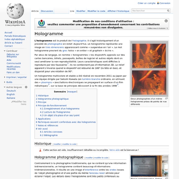
Holographie Un article de Wikipédia, l'encyclopédie libre. On produit un hologramme en éclairant un objet par une source de lumière cohérente (laser) et en enregistrant sur une surface sensible (par exemple, une plaque photographique) les franges d’interférences obtenues en combinant l’onde émise par la source laser (onde de référence) et l’onde réfléchie par l’objet. Lors de la « restitution » de l’image holographique, l’hologramme est éclairé par un laser (voire par une lumière non cohérente) et il agit alors comme un réseau de diffraction, pour former une image en relief de l’objet initial. Un avantage de cette technique est que chaque morceau d’hologramme peut restituer la même image que l’hologramme entier vu sous un certain angle, netteté mise à part, même si l’on a cassé la plaque. Au lieu d’être produit à partir d’un objet réel, un hologramme peut être aussi calculé par un ordinateur à partir d’une image de synthèse en 3D. Principe[modifier | modifier le code] est : où est donnée par : et
Modeling the Mirascope Using Dynamic Technology - 3. Mirascope Construction Using Geogebra 3.1 Define Two Parabolas Algebraically In order to align the two parabolic mirrors accurately, we use algebraic functions to model the two face-to-face parabolas. We start with two constant variables, a and c, where a controls the orientation and curvature of the parabolas, and c controls their vertical alignment or, in our case, the distance between the vertices of the two parabolas. Figure 5: Construct two parabolas using an algebraic approach. [Open a dynamic GeoGebra worksheet in a new window.] 3.2 Modeling Light Reflections Within the Mirascope According to the previous analysis, we start with a point P, which represents an arbitrary point on the object placed at the bottom of the mirascope. To locate the image of point P outside the mirascope, we need at least one more light ray that originates from point P and reaches the upper mirror at a different point, for example, point H. [Open a dynamic GeoGebra worksheet in a new window.] [Open a dynamic GeoGebra worksheet in a new window.]
Modeling the Mirascope Using Dynamic Technology - Additional Figures Figure 4c: Two light rays that are parallel to the -axis reach an upward parabola. Figure 4d: Hide the intermediate steps to reduce the construction complexity. Figure 6a: A light ray from point reaches the upper parabola and is reflected to the lower one. Figure 6b: A light ray from point is reflected out of the mirascope. Figure 6d: Defining a new tool to reflect light from point out of the mirascope. Figure 6e: Using the newly defined tool to reflect a second light ray from point out of the mirascope. Figure 7c: Modeling more light rays from point is not necessary to locate the image of . Figure 7d: The image is well above the mirascope if the two parabolas are relatively close to each other. Figure 7e: Finding the appropriate opening by tracing the outgoing light rays. Figure 9: When the eye, the object, and the focus of a parabolic mirror are aligned in certain ways, one may be able to see a clear image with changes in its size and orientation.
Stéréoscopie Un article de Wikipédia, l'encyclopédie libre. Stéréoscope de Holmes Stéréoscope de poche La stéréoscopie (du grec stéréo- : solide, -scope : vision) est l'ensemble des techniques mises en œuvre pour reproduire une perception du relief à partir de deux images planes. Elle est née pratiquement en même temps que la photographie, bien que des traces plus anciennes dans des interrogations et expérimentations picturales soient trouvées. Ainsi, la collection Jean-Baptiste Wicar du Palais des beaux-arts de Lille conserve deux dessins distinguant les visions d'un même sujet pour chaque œil, exécutés par Jacopo Chimenti, peintre de l'école florentine (1554 - 1640). Il existe, pour réaliser ces images, aussi bien que pour les observer, une grande variété de moyens, à la description desquels plusieurs centaines de livres ont été consacrés. Physiologie[modifier | modifier le code] Observation en relief[modifier | modifier le code] Réalisation[modifier | modifier le code] Appareil stéréo des années 1930.
Modeling the Mirascope Using Dynamic Technology - 4. Using the Simulation: Explorations and Exercises Once we have constructed a mathematical mirascope, we can use it to ask in-depth questions about the mirascope and the way it works. In this section, we discuss how the simulation can be used for exercises and open-ended explorations. 4.1 Is the Whole Image Visible? First of all, we want to see how an object placed at the bottom of the mirascope can be projected outside, using the “Trace On” feature of GeoGebra. Figure 7a: A small shape is projected to the top part of the mirascope; only part of the image is actually visible. To address the problem above, we can explore the effects of the vertical distance between the two parabolas on the position of the image. Figure 7b: When the two parabolas are far apart, a small shape is projected within the mirascope, invisible to the observer. [Open a dynamic GeoGebra worksheet in a new window.] 4.2 Are More Light Rays Necessary to Locate the Image of a Point? 4.3 Exercises Exercise 1. Exercise 2. Exercise 3. Exercise 4. Exercise 5.
Modeling the Mirascope Using Dynamic Technology - 1. Introduction Author(s): Lingguo Bu (Southern Illinois University Carbondale) The mirascope is a toy made of two parabolic mirrors that fascinates children and adults alike. Figure 1a: A mirascope projects a small object placed at the bottom to the top [photo taken by author]. Figure 1b: A mirascope consists of two parabolic mirrors [photo taken by author]. Lingguo Bu (Southern Illinois University Carbondale), "Modeling the Mirascope Using Dynamic Technology - 1.