Qucs project: screenshots
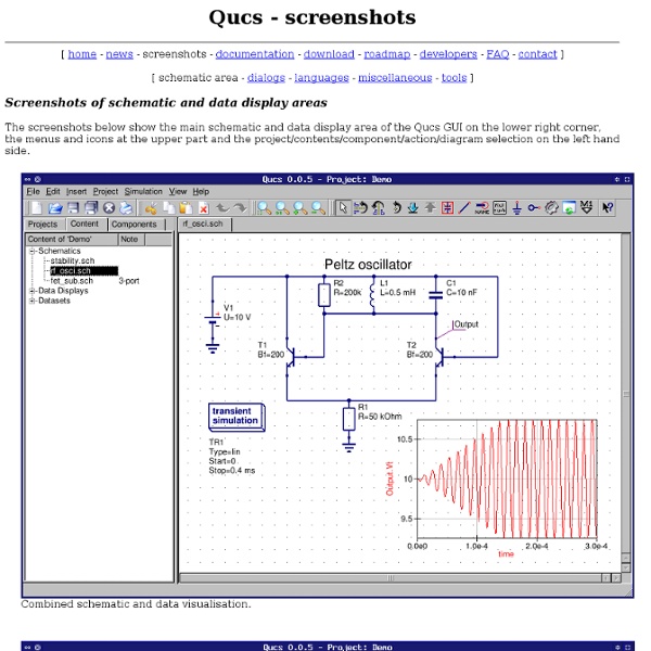
[ schematic area - dialogs - languages - miscellaneous - tools ] Screenshots of schematic and data display areas The screenshots below show the main schematic and data display area of the Qucs GUI on the lower right corner, the menus and icons at the upper part and the project/contents/component/action/diagram selection on the left hand side. Simple filter in qucs-qt4 Combined schematic and data visualisation. Simple schematic area. Data display with different kinds of data representations (diagrams) and data markers. Data display with 3D diagram. Please note that the actual appearance depends on the window manager (window decorations), the selected type of font and its size and the widget set can be selected by the qtconfig program.
conception_electronique
Le monde de la CAO en électronique est très fortement dominé par des gros logiciels propriétaires et payants (chers!!) tel que Protel, Cadence principalement à cause de l'ultra-spécialisation de ces logiciels. La conception électronique assistée par ordinateur comporte plusieurs phases : dessin schématique du circuit, simulation, placement des composants, routage. Synthèse, Simulation : Alliance : logiciel libre de design de circuit intégré VLSIXilinx ISE Webpack : logiciel pour la synthèse/implémentation de VHDL sur circuit FPGA Xilinx (non-libre mais gratuit) Quartus Web Edition : logiciel pour la synthèse/implémentation de VHDL sur circuit FPGA Altera (non-libre mais gratuit) Remarque : les sites de Xilinx et Altera proposent aussi une version gratuite de l'outil de simulation non-libre Modelsim. Simulation : GHDL : logiciel libre de simulation de code VHDLGtkWave : logiciel libre de visualisation de simulationSimili : logiciel de simulation VHDL (non-libre mais gratuit)
The universal simulator
I-V Curve
Using the related tool bar button (the one on which M1 is written), you can put markers on the curves plotted. At this point you can verify, from the two points that the variable lambda is 0.4; this is where this tool is very handy for me : it gives exactly what you calculate by hand, provided that you set device parameters accordingly. Event hough, this sounds very normal, it is never the case for commercial simulators since they use extremely complicated models that are extracted for a specific technology. So sometimes you loose the taste of the initial design phase :) in which everything is under control. For having the idea on how to do the verification mentioned above, you can also see another tutorial performed with another tool but the idea is exactly the same. (See especialy Method #1 in that tutor) But we will do the same thing here in this tutorial as well.
ARM creators Sophie Wilson and Steve Furber [printer-friendly]
Unsung Heroes of Tech The Story so Far At Acorn, Sophie Wilson and Steve Furber have designed the BBC Micro, basing the machine on the ageing MOS 6502 processor. Their next challenge: to choose the CPU for the popular micro's successor. Now read on... While Sinclair attempted to move upmarket with the launch of the QL in early 1984, Acorn was trying to invade Sinclair's lucrative low-end territory with a cut-down version of the BBC Micro, to be called the Electron. MOS' 6502: good enough for the Electron, not the BBC Micro's successor While Acorn was heading into cash-flow problems, Wilson and Furber had already become engaged in what would prove to be the biggest adventure of their lives. By 1983, the 8-bit 6502 processor had outlived its shelf life, and Wilson and Furber had been experimenting with available 16-bit processors to power their next machine. Hauser had even gone to the lengths of hiring three integrated-circuit designers and buying in chip design tools and workstations.
Apple iPhone charger teardown: quality in an tiny expensive package
Disassembling Apple's diminutive inch-cube iPhone charger reveals a technologically advanced flyback switching power supply that goes beyond the typical charger. It simply takes AC input (anything between 100 and 240 volts) and produce 5 watts of smooth 5 volt power, but the circuit to do this is surprisingly complex and innovative. How it works The iPhone power adapter is a switching power supply, where the input power is switched on and off about 70,000 times a second in order to get the exact output voltage required. In more detail, the AC line power is first converted to high voltage DC[1] by a diode bridge. The side view above shows some of the larger components. Next, the high voltage DC is chopped at high frequency by a MOSFET switching transistor, which is the large three-pinned component in the upper left. The picture above shows the flyback transformer (yellow) more clearly, above the USB jack. The circuit in detail The primary The secondary Isolation Schematic Transformer teardown
openchronos-ng / Wiki / Home
How FPGAs work
How FPGAs work Logic-cells FPGAs are built from one basic "logic-cell", duplicated hundreds or thousands of time. A logic-cell is basically a small lookup table ("LUT"), a D flip-flop and a 2-to-1 mux (to bypass the flip-flop if desired). The LUT is like a small RAM that can implement any logic function. Interconnect Each logic-cell can be connected to other logic-cells through interconnect resources (wires/muxes placed around the logic-cells). IO-cells The interconnect wires also go to the boundary of the device where I/O cells are implemented and connected to the pins of the FPGAs. Dedicated routing/carry chains In addition to general-purpose interconnect resources, FPGAs have fast dedicated lines in between neighboring logic cells. Older programmable technologies (PAL/CPLD) don't have carry chains and so are quickly limited when arithmetic operations are required. >>> NEXT - part 3: Internal RAM >>>
Related:
Related: