
Système Adafruit apprentissage Introducing Bluefruit EZ-Link The ultimate serial Bluetooth link & wireless Arduino programmer We are excited to add another product to our growing Adafruit Bluefruit line, this time its the Bluefruit EZ-Link: the best Bluetooth Serial Link device ever made. Adafruit 2.8" Color TFT Touchscreen Breakout v2 Color! Add some jazz & pizazz to your project with a color touchscreen LCD. Wireless Music Veto Button for your Office Exercise your right to skip songs in the office! This project uses the comically large "big red button" to cast your negative vote for the music that's playing on Spotify. Adafruit NeoPixel Überguide Everything you always wanted to know about Adafruit NeoPixels but were afraid to ask NeoPixels are “intelligent” full-color RGB LEDs that can be controlled and chained from a single microcontroller pin. Connecting a 16x32 RGB LED Matrix Panel to a Raspberry Pi How to connect a 16x32 RGB LED display to your Raspberry Pi This tutorial uses C code to drive the display. A look inside!
diyembedded.com Basic Triac and SCR Projects and Circuits by Lewis Loflin This page will discuss basic triacs and SCRs. A triac is a bidirectional, three-terminal dual, back-to-back Thyristor (SCR) switch. This device can switch the current in either direction by applying a small current of either polarity between the gate and one of the two main terminals. If one is not familiar with diodes and AC rectification see the following: Turning a Diode On/Off Pictured above is a silicon controlled rectifier (SCR) or thyrister. Note that the ON switch is referred to as 'normally open' (N.O.) and makes (closes) a connection when pressed. In the circuit above the Load is a DC motor. In this example we have placed a diode in series with the gate on/off switch. In this circuit example we have placed variable resistor (potentiometer) in series with the gate diode. Here we use full-wave pulsating DC with a SCR. This illustrates to process with full-wave unfiltered D.C. In another note we can control full-wave pulsating unfiltered DC with a thyristor. Snubbers
Tutoriels Arduino - Ethernet + SD Whatsit? We just got the latest version of the Arduino Ethernet shield with a MicroSD card slot and I promised Bill Greiman I'd try out the latest version of his SdFatLib library so I decided to code up a simple Webified file browser. Its a quicky project and demonstrates what you can do, but it isn't 100% perfect so you should be ready to modify it if you'd like to do other stuff, 'K? This is a good beginning to a logging web-monitor, or remote storage system. Get familiar Initializing Micro-SD card on an Ethernet shield The latest Arduino Ethernet shield comes with a handy MicroSD card slot so that you can store and retrieve data through the shield. Be sure to have the very latest version of SdFatLib , as you'll need some of the newer capabilities! First thing to note is that the SS (Slave Select) pin for the card is digital 4 (although as of the writing of this mini-tutorial, the schematic hasn't been updated, you'll have to trust me!) uint8_t r = card.init(SPI_HALF_SPEED); To: List files
RF24Network for Wireless Sensor Networking | maniacbug RF24Network is a network layer for Nordic nRF24L01+ radios running on Arduino-compatible hardware. It’s goal is to have an alternative to Xbee radios for communication between Arduino units. It provides a host address space and message routing for up to 6,000 nodes. Today, I managed to get 17 nodes running on a single network. Hardware The fastest way to get RF24Network-compatible hardware is to build the Getting Started board, or the ProtoShield board as explained in other posts, attached to commercially-available Arduino. Ultimately, I wanted something smaller, cheaper and more power-efficient, so I built a Low Power Wireless Sensor Node. Simple Transmit/Receive The Hello World examples illustrate how simple it is to communicate between two nodes. There are three simple sections: Static Initialization First, the static setup to prepare the radio, and set the addresses. setup() Second, the ‘setup()’ simply prints out a quick salutation, and initializes the radio layers. Transmitter loop()
Debian 7 Wheezy Dedicated Web Server Setup Step by Step Debian 7.0 Wheezy has been officially released on May 5, 2013. Wheezy is powered by Linux kernel 3.2 and multiarch support. Concerning LAMP software, Apache 2.2.22 MySQL 5.5.30 and PHP 5.4.4 are included. In this post I describe a dedicated server setup, using Debian Wheezy. I use Dyn.com for all my DNS and e-MAIL needs, so I will not setup name server or a full blown mail server. I selected a minimal Debian amd64 server (basic Debian system and SSH). Connect using SSH This is the first and should be the last time you are remotely connected with the server as : Change root password Use: remove /robot.sh This step concerns only Hetzner servers. (symbolic link to ) is just for reporting a successful install and should normally have been removed immediately. If is present, will fail with the following message Perform a full system update Using : Update files database Color Bash Prompt To add color to bash prompt, you can follow this guide, where a global solution is provided (recommended). uncomment
Débuter avec Arduino! - Chapter Zero «tronixstuff Hello world! Updated 24/11/2012 Please join with us as we learn about electronics and the Arduino! So let’s get started… There are over fifty chapters in this series, however you should start here (chapter zero). Getting Started with Arduino (Massimo Banzi) and also assume a basic knowledge of electronics. If you would prefer an off-line method of learning, or would like a great book on the topic – consider my book “Arduino Workshop” – it’s the best book on the market for a complete beginner to learn about Arduino. First of all, let’s breakdown the whole system into the basic parts. Arduino is an open source physical computing platform based on a simple input/output board and a development environment that implements the Processing language (www.processing.org). So, we have hardware and software. Our software is the IDE – software very similar to a word-processor, but can send the Arduino program (or “sketch”) to the micro controller. Now for the Arduino itself. Great! How did you go? Notes:
The WorkerB! I have received 5 test PCBs today of the unnamed ‘ATMega32u4+nRF24L01′ board project that I described earlier, I decided to call it a ‘Worker Bee’ or WorkerB! as its task will be to collect and transmit data. The final PCB layout slightly differs from what I last published, I did some more reshuffling, added a RESET button, a solder jumper to allow battery level measurement via Analog 0: There is an option to power the thing from a single AAA battery via the optional LTC3525 boost regulator, the battery is placed on the back via two battery holders. Some pictures: I have also designed a RFM12b breakout that can be used instead a nRF24L01: A Better Serial.print() For Arduino | Utopia Mechanicus In a previous article I described how to add the old-fashioned print() function to Arduino to improve debugging – after all, it gets tedious to use a separate Serial.print() function for each type – and inserting information into a string is printf’s specialty. However, while I found they did the job, they weren’t quite what I wanted. for one thing, the memory they used for the format string is in RAM, which means it contributes to ‘eating up’ the 2k memory that the ATMega328 on the Arduino has to use. Any string does this, of course, but prints can eat up string space quickly, especially if you add a lot of debugging code. Another problem when I mentioned the code to others seemed to be the waste of space for the buffer character array. However, this wasn’t a big issue, since the buffer only existed for the time the function was around – and in tight memory situations, it could be shrunk by editing the length. With But of course it becomes really handy with those long entries:
Travaux Pratiques Arduino Introduction La plateforme utilisée pour les travaux pratiques est la carte Arduino. Préliminaires installez sur votre poste de travail l'environnement de développement Arduino installez sur votre poste de travail l'environnement de développement Processing optionnel : installez l'éditeur de montage Fritzing. Documentation Premières Manipulations Dans cette première partie, vous allez tester quelques programmes (appelés sketch) de base et les montages associés. Clignotement d'une LED Cette première manipulation permet de s'acclimater avec l'atelier Arduino, au chargement du programme sur la carte. L'Arduino Uno est équipé de 13 entrées-sorties digitales (0,1) d'une tension de 0V ou 5V. Cette manipulation montre la configuration d'une ES (13) en mode sortie (OUTPUT) et le positionnement en 0 ou 1 (LOW pour 0V et HIGH pour 5V). explications, code et montage (CIRC01) Gradation d'une LED avec le PWM Boutons poussoirs explications, code et montage (CIRC07) Liens
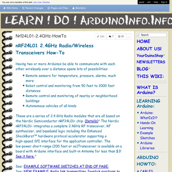
NRF24L01 real life range test | Charles-Henri Hallard Today I was working on a project using NRF24L01 chipset and I decided to verify the test range of this small device that you can buy as a breakboard on ebay. I bought a pair some time ago and bought recently another for my new projects. The modules are different but have the same pinout so it is easy to change them for testing. Both modules are new version, NRF24L01+ and not the old version NRF24L01. The new version is capable of doing 250KBPS low speed and the old not. The newest is the black on the left of the picture, seems better quality and a little shorter. nrf24L01-black nrf24L01-green Of course I used the same module on both Arduino. // Max power setPALevel( RF24_PA_MAX ) ; // Min speed (for better range I presume) setDataRate( RF24_250KBPS ) ; // 8 bits CRC setCRCLength( RF24_CRC_8 ) ; // Disable dynamic payloads write_register(DYNPD,0); // increase the delay between retries & # of retries setRetries(15,15); Then, I went outside in a clean area. nrf24L01-PA-LNA nrf24L01-Antenna
Connecting an Arduino Pro Mini with an FTDI Friend (Shallow Thoughts) I found myself wanting to upload a sketch to an Arduino Pro Mini recently, using an FTDI Friend, and found that how to do it was surprisingly undocumented. First, the important thing is that the six FTDI pins do match up with the six pins at the edge of the Pro Mini, though obviously you have to figure out which way to rotate the two boards so you won't be 180 degrees off. I wasn't clear on that since the labels on the pins don't seem to match (see below). Second, if you haven't soldered headers to your Pro Mini, you can stick a female-female header into the FTDI Friend's female header. then insert the other side of the header into the holes in the Pro Mini at an angle -- hold them with some tension so that the header pins are making contact with the copper-plated rims of the Pro Mini holes. Okay, so the big question is which way to match the pins. It's complicated by the Pro Mini's having both outer holes unlabeled. So ignore Ground and use VCC as your guide.
Temperature controlled soldering iron My Weller TCP magnastat iron broke, the magnetic switch stuck open circuit. This is the second time in three years this has happened. Needless to say I was feeling a little hacked off about this given the price of spares for this iron, the magnetic switch retails at approximately £30.00. Twenty four Volt AC, 48 Watt Chinese temperature controlled irons ( heating element + temperature sensor ) can be purchased on Ebay for £9.99 inc. shipping from a UK distributor - an incredible price. A temperature controller circuit was designed and tested for this iron using junk box parts, the result of which is shown here. No data for the iron was available so a little experimenting was carried out. The controller circuit uses a 741 op amp configured as a comparator to switch the relay contacts feeding power to the iron heating element. All of the components came from the junk box. The soldering iron itself has a very good ergonomic feel - as good as the Weller, in fact it looks like a copy.