
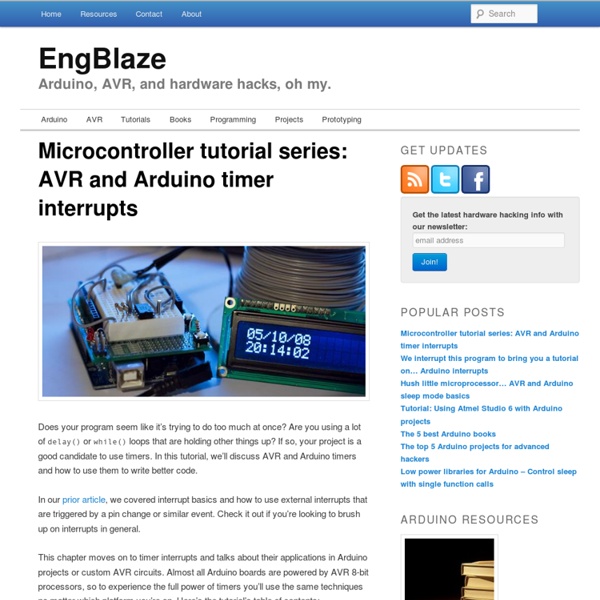
Studfinder: Wire Edition - CraigM Craig Macomber, Milda Zizyte June 10, 2011 Often, humans are faced with the problem of finding that which they cannot see. The five senses are limited and in particular do not extend to wavelengths outside the audible or visible spectrum. Such sensing capabilities are conceivably very important. In particular, humans cannot easily locate electric fields. In fact, the robot Marvin faces the same problem humans do - just as a robot cannot see these electric fields, neither can humans. Our solution combines analog filtering with digital processing to achieve its goal. The analog circuit has three main purposes: To receive and filter an input electrode current into a clear voltage output signalTo convey the output using minimal complexityTo effectively interface with an Arduino Uno for digital processing (1) is the most complex, requiring filtering a current source. (2) is accomplished by the use of three LEDs, denoted “left,” “right,” and “amplitude.” (3) strongly depends on (1) and (2). 1.
CommentReparer.com - Apprenez à tout réparer Welcome Tout réparer (ou presque) | SUV [sens & utilités en vrac] A l’heure où la grogne contre l’obsolescence programmée devient de plus en plus audible, on me demande souvent comment réparer des produits : ces chaussures irréparables, ces faux contacts dans les écouteurs si frustrants. En tant que passionnée du hack, de la réparation, et du détournement, je n’avais pas de solution pour bien des objets jusqu’à ce que je découvre Sugru, une sorte de pâte à modeler en silicone qui permet de réparer tout ou presque. Cette très belle vidéo de Do the Green Thing donne une petite idée des portes de la créativité qui s’ouvrent à vous. The Joy of Fix from Do the Green Thing on Vimeo. On peut réparer les roues usées de sa valise de voyage, un câble, et beaucoup d’autres choses encore : regardez cette vidéo où on vous fait – avec humour – une démonstration des choses que l’on peut faire. L’idée derrière ce produit: permettre à chacun de réparer et adapter les produits à leurs besoins. Vous ne savez pas comment faire? Une poignée cassée: une réparation discrète
Ready, Set, Oscillate! The Fastest Way to Change Arduino Pins « The Mind of Bill Porter There are many ways to change an output pin. The way we know and love is the famous digitalWrite() function. (Spoiler: Want a faster digitalWrite? Download Here!) But even the Arduino Reference claims that it is not the most efficient. I ran some tests to find out. The estimated CPU cycles is calculated from ½ the waveform period measured divided by the period of 16Mhz, since it takes two write operations to complete a full period in a waveform. The 3 methods I tested were digitalWrite(pin, LOW); digitalWrite(pin, HIGH);CLR(PORTB, 0) ; SET(PORTB, 0);PORTB |= _BV(0); PORTB &= ~(_BV(0)); The macros used: #define CLR(x,y) (x&=(~(1<<y))) #define SET(x,y) (x|=(1<<y)) #define _BV(bit) (1 << (bit)) The results As you can see, digitalWrite takes around 56 cycles to complete, while direct Port addressing takes 2 cycles. Next I tested just flipping a pin. digitalWrite(pin, ! #define sbi(port,bit) (port)|=(1<<(bit)) Wow, the Arduino method takes a whopping 121 cycles to flip a pin!
Burn a bootloader to a blank atmega328/atmega328p with an Arduino UNO | 3guys1laser.com Build your own optiLoader shield! You cant use your Arduino UNO as programmer unless you modify it, but i didnt want to do that! Some people had luck using a Resistor and Capacitor to disable the auto reset feature but it did not work for me (Using an Arduino UNO R2) So i tried using a parallel port programmer but never got it to work. It seems easy, so if your interested go ahead and try it yourself, but be warned, could lead to frustration :) Fortunately Bill Westfield wrote optiLoader! The readme file doesent tell you how to connect the blank chip so i asumed that you need an oscillator and a pull up resistor and... well... it worked! You need: Working Arduino (with µC and Bootloader) - optiLoader will run on that one16MHz oscillator2 x 22pF ceramic capacitor10KΩ resistor Breadboard setup looks like this: Powering the circuit over pin 9 is questionable, but seems to work well with this setup (look at optiLoader source files for more info on this).
Python Arduino and Python Talking to Arduino over a serial interface is pretty trivial in Python. On Unix-like systems you can read and write to the serial device as if it were a file, but there is also a wrapper library called pySerial that works well across all operating systems. After installing pySerial, reading data from Arduino is straightforward: >>> import serial >>> ser = serial.Serial('/dev/tty.usbserial', 9600) >>> while True: ... print ser.readline() '1 Hello world! Writing data to Arduino is easy too (the following applies to Python 2.x): >>> import serial # if you have not already done so >>> ser = serial.Serial('/dev/tty.usbserial', 9600) >>> ser.write('5') In Python 3.x the strings are Unicode by default. >>> ser.write(b'5') # prefix b is required for Python 3.x, optional for Python 2.x Note that you will need to connect to the same device that you connect to from within the Arduino development environment. Any write() commands issued before the device initialised will be lost. Py2B
Syncronized Serial communication with Arduino Greetings everyone,I have been working on developing a custom serial 'protocol' for communicating data from a PC to an arduino; specifically for driving a 8x8 LED matrix from audio levels (among other things) Now I had planned to send 8 bytes at a time, 1 byte for each row or column, with values from 0 to 255... But I have run into some problems:1) How to signal 'start' or 'end' of a packet of 8 bytes so that the display isn't refreshing with half of one frame and half of another seeing as though each byte needs to range from 0 to 255... and all useful ASCII characters fall within that range.I was thinking of possibly using multiple-byte start/end codes as well as explicitly counting the read bytes once a start byte(s) is read. 2) since the clock speed of the arduino is quite a bit faster than a 9600 baud rate (Side question: any drawbacks/caveats with higher serial baud rates?), how to make sure that either a) the full 8 bytes is available (delay?
Blended Technologies » Blog Archive » Realtime Plot of Arduino Serial Data Using Python So I got an Arduino a few weeks ago, and just made my second little project: It simply has a piezo element connected to an analog input pin. The Arduino polls the value every 100ms and prints it to the serial port. Here is the sketch: /* Knock Poller * ---------------- * We listen to an analog pin, sample the * signal and write it to the serial port. */ int knockSensor = 5; byte val = 0; void setup() { Serial.begin(9600); } void loop() { val = analogRead(knockSensor); Serial.println(val,DEC); delay(100); // we have to make a delay to avoid overloading the serial port } The problem was that I found it was hard to tell what was happening just by reading the values printed to the serial monitor in the Arduino IDE’s serial monitor. So I researched realtime plots/graphs/charts in Python, and sadly didn’t find too much. I repurposed it to listen to the Arduino and set it listening: You can see how my pushing on the knock sensor makes the voltage go up and down. You can get the code here. Update:
InterfacingWithSoftware You have come to the place to learn about connecting an Arduino to other devices, whatever software is running on those other devices. The Arduino can "talk", (transmit or receive data data) via a serial channel, so any other device with serial capabilities can communicate with an Arduino. It doesn't matter what program/programming language is driving the other device. You can either use the Arduino's "main" serial port, the one it uses when you "talk" to it to program it, or you can leave that channel dedicated to programming (and the development environment's serial monitor), and use two other pins for an extra serial link dedicated to the external device. Some programs (like Flash) don't have native serial capabilities. CmdMessenger messaging library A Messaging library for both Arduino and C# .NET / Mono. Commands that can be sent or received. Instrumentino is an open-source modular graphical user interface framework for controlling Arduino based experimental instruments. For Mac