patterns & practices: Project Silk
Visual Studio ALM - Plan Manual Tests using Team Web Access
Create test plans to track manual testing for sprints or milestones. That way you can see when the testing for a specific sprint or milestone is complete. With TFS 2013 Update 3, you can customize test plans and suites. For example, add an extra field to identify the reviewer for a test plan, or change the default values for the state field to fit your process better. For additional changes introduced with TFS 2013.3, review the Q & A section. If you haven't already, create your team project and create your backlog. Now you've created a requirement-based test suite for each backlog item. A: If you are using on-premises TFS with TFS 2013 Update 3, you can edit the properties of test plans and test suites from Team Web Access or Microsoft Test Manager (MTM). From the Test hub in Team Web Access, select a test plan or test suite and then open it. With Update 3 for MTM and TFS 2013 Update 3 installed: You can edit the properties of the work item from MTM too. A: Yes. A: Yes. A: Yes. A: Yes.
The UML Model Explorer - Skinner's Blog
In the VSTS 2010 Architecture product, we've added another toolwindow to VS designed to help you understand and manipulate the UML models that you will be building. The UML Model Explorer ( that's what we're currently calling it, but that can certainly change :) ) is a WPF component that represents the UML Package hierarchy of your models. "Models" in this context refer to the contents of the Modeling projects you have created and added to the current solution. The root node or nodes of the UML Model Explorer are UML packages representing those Modeling Projects. For example, in the image below, I have created two Modeling Projects, "My First Modeling Project" and "My Second Modeling Project". You'll notice that the UML Model Explorer has two corresponding nodes in the tree. You might immediately be asking yourself "What's up here? As I mentioned earlier, every time you create a Modeling Project, a new node will be displayed in the UML Model Explorer. Adding Elements Summary
patterns & practices: App Arch Guide 2.0 Knowledge Base
Chemie online lernen - kostenlose Kurse im Überblick
Im Internet tummeln sich viele Online-Kurse, mit denen Sie Chemie lernen können. Wir stellen Ihnen drei der kostenlosen Anbieter mit diesem Praxistipp näher vor. Chemieseiten: Hilfreich für alle Chemie-Interessierten Chemieseiten bietet ein umfangreiches Angebot an Lernmaterialien zur Verfügung. Mindpicnic: Umfangreiches Online-Lernangebot mit Anmeldung Mindpicnic bietet neben Chemie auch noch andere Fächer zum Üben an, was das Angebot sehr vielseitig macht. Chemiekiste: kostenlos Quizzen bis zum Umfallen Chemiekiste bietet neben den vielen theoretischen Ansätzen auch die Möglichkeit an, sich im Quiz zu beweisen. Fazit: Für jeden das passende Angebot Bevor Sie online Chemie lernen möchten, sollten Sie sich fragen, welches Ziel Sie verfolgen und welche Vorkenntnisse Sie bereits haben. Kommentar schreiben
How to: Create UML Modeling Projects and Diagrams
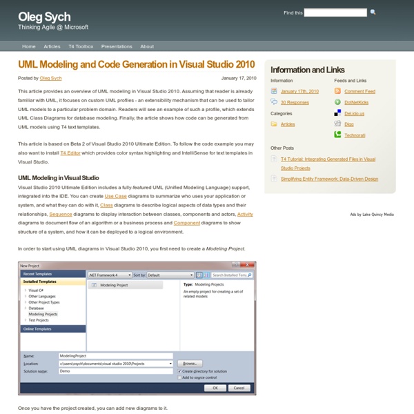
UML models help you understand, discuss, and design software systems. Visual Studio provides templates for five of the most frequently used UML diagrams: activity, class, component, sequence, and use case. In addition, you can create layer diagrams, which help you define the structure of your system. UML modeling diagrams and layer diagrams can exist only inside a modeling project. Each modeling project contains a shared UML model and several UML diagrams. Each diagram is a partial view of the model. To see which versions of Visual Studio support this feature, see Version support for architecture and modeling tools. To create a diagram and add it to a project On the Architecture menu, choose New UML or Layer Diagram.In the Add New Diagram dialog box, click the type of modeling diagram that you want. If your solution is open, the new project is added to the solution. If you already have a modeling project, you can also use the following procedure. To create a blank modeling project
ploeh blog
Transputer - WikiVisually
IMSB008 base platform with IMSB419 and IMSB404 modules mounted The transputer was a series of pioneering microprocessors of the 1980s, featuring integrated memory and serial communication links, intended for parallel computing. It was designed and produced by Inmos, a semiconductor company based in Bristol, United Kingdom.[1] For some time in the late 1980s, many[2] considered the transputer to be the next great design for the future of computing. Background[edit] In the early 1980s, conventional CPUs appeared to reach a performance limit. It seemed that the only way forward was to increase the use of parallelism, the use of several CPUs that would work together to solve several tasks at the same time. A side effect of most multitasking design is that it often also allows the processes to be run on physically different CPUs, in which case it is known as multiprocessing. Design[edit] Originally the plan was to make the transputer cost only a few dollars per unit. Architecture[edit]
visual studio - Reverse Engineering Code into a UML Class Diagram in VS 2010
Domain Driven Design: A Step by Step Guide - Part 2
This is the second part in a series on Domain Driven Design. You can read the first part here. This article was created and edited (with permission) from a series of posts on Casey's blog. Entities and Value Objects Entities and Value Objects (VO) form the core building blocks of Domain Driven applications. Why has it taken this long to get to something so fundamental? DDD has refined this concept a little, by splitting the idea of these business objects into two distinct types, Entities and Value Objects Entities “this is my Entity, there are many like it, but this one is mine” The key defining characteristic of an Entity is that it has an Identity – it is unique within the system, and no other Entity, no matter how similar is the same Entity unless it has the same Identity. Examples of common Entities are: Customer, Product, Container, Vehicle Whichever way you choose to represent it, an Entity is defined by having an Identity. Value Objects Hey, I’ve Heard of These, We Have Them in .Net!
As We May Think
“As We May Think” (deutsch: „Wie wir denken könnten“) ist ein Essay des amerikanischen Ingenieurs Vannevar Bush, der 1945 in der Zeitschrift The Atlantic Monthly publiziert wurde. Bush entwirft darin das Konzept der universalen Wissensmaschine Memex (Abkürzung für Memory Extender), die als Vorläufer von Personal Computer und Hypertext gilt. Parallel mit As We May Think veröffentlichte Bush einen Bericht an den amerikanischen Präsidenten („Science – The Endless Frontier“), der die staatlich geförderte Vernetzung von Wissenschaft, Industrie und Militär empfiehlt. Entstehungs- und Wirkungsgeschichte[Bearbeiten | Quelltext bearbeiten] Bush skizzierte das Memex-Konzept erstmals im Jahr 1939. Viele Computer-Pioniere sahen rückblickend in Bushs Memex-Konzept den Ausgangspunkt der intuitiven Interaktion zwischen Mensch und (Rechen-)Maschine. Engelbart bezeichnet dieses Projekt später als “Augmentation of Man's Intellect” (deutsch: „Vergrößerung des menschlichen Intellekts“).