background preloader

Improving the Beginner’s PID – Introduction « Project Blog

Improving the Beginner’s PID – Introduction « Project Blog
In conjunction with the release of the new Arduino PID Library I’ve decided to release this series of posts. The last library, while solid, didn’t really come with any code explanation. This time around the plan is to explain in great detail why the code is the way it is. People directly interested in what’s going on inside the Arduino PID library will get a detailed explanation. It’s going to be a tough slog, but I think I found a not-too-painful way to explain my code. The Beginner’s PID Here’s the PID equation as everyone first learns it: This leads pretty much everyone to write the following PID controller: Compute() is called either regularly or irregularly, and it works pretty well. Sample Time – The PID algorithm functions best if it is evaluated at a regular interval. Once we’ve addressed all these issues, we’ll have a solid PID algorithm. UPDATE: In all the code examples I’m using doubles. Tags: Arduino, Beginner's PID, PID

HMC5883L Compass Tutorial with Arduino Library - Tutorials - Love Electronics Using a magnetometer can be a little tricky, especially if your unsure about the formulas to use to get the correct bearing and when other magnetic objects are interfering with your signal. We've created a library for our HMC5883L Breakout Board , which will also be compatible with other HMC5883L breakout boards made by other manufacturers. Join us whilst we cover the following: Understand what is a magnetometer and how they work. Introduce the HMC5883L Arduino Library Explain how to extract data from the HMC5883L. How do compasses work? Firstly an introduction, a (standard handheld) compass works by aligning itself to the earths magnetic field. Our magnetometer uses these magnetic fields, however it doesn't pull on a little needle inside it! How do we use one? Okay, so now we know how to use one, the first step is to get some data out of our compass. Once you have the library installed start your Arduino IDE and we can get coding. Using the HMC5883L Arduino Library Wire.begin();

RGB Accent Lighting with Remote Control Our good friend Tod Kurt, of ThingM, shows how to control a strip of RGB LEDs using the BlinkM MaxM driver and a FreeM IR remote receiver. I used some similar strip lighting and a MaxM for a friend’s Halloween costume, and really liked being able to program the blink pattern via Arduino. The addition of an IR remote opens up interesting possibilities. Invisible Accent Light with BlinkM MaxM & FreeM Related

Linear Actuator - PID Control A linear actuator is a motor that has been geared to extend and contract an arm rather than rotate a shaft. Many applications that use linear actuators require precise position control, but since DC motors can ordinarily only be told how fast to go (on a scale from -100% and 100% duty cycle) you need to program a control system. In order to make a control system, you'll need a linear actuator that has a built-in feedback device such a as a potentiometer. Introduction This application guide is designed to explain the basics of PID control and how to implement a basic control loop using Phidgets. Phidgets The following setup was used to build this application guide: You could use the 1064_1 - PhidgetMotorControl HC instead, but it doesn't have an analog input for the feedback device, so you'd also need to use a device with an analog input and change the program accordingly in this case. PID Control Basics Proportional Control Integral Control Derivative Control Sample Program ActuatorPID Algorithm

Régulation PID, comment la régler 1/2 | rhaaa Étant donné que je n’ai pas encore tout le matériel nécessaire pour avancer mes autres projets, j’en profite pour approfondir un peu mes connaissances théoriques et vous en fait donc profiter. Mon projet ici est simple : Réguler une température à l’aide d’un microcontrolleur, mais surtout bien comprendre les tenants et aboutissements des différents réglages et algorithmes. L’objectif ici n’est pas tant d’expliquer ce qu’est un PID, ni comment il fonctionne dans le detail, mais plutôt de donner une méthode permettant d’approximer les coefficients du régulateur. Je profiterais de cette expérience pour faire 2 articles : – celui-ci concernant le PID a proprement parler – Un second article concernant ma méthode pour obtenir des courbes « lives » a partir d’un arduino et d’un PC. Qu’es-ce qu’un PID Pour simplifier, on parlera dans la suite de régulation de température, vu que ce sera notre application ici. Formule PID, source ControlGuru Description du materiel Méthode de réglage Définitions Avec:

xoscillo - A software oscilloscope that acquires data using an arduino or a parallax (more platforms to come). About This is a multiplatform software oscilloscope and logical analyzer. It supports arduino(with custom firmware) and a Parallax USB oscilloscope. More platforms to come. Features Panoramic view Load and save waveforms Zoom in and out Can open several waveforms at the same time Can run several oscilloscopes/logical analyzers simultaneously Frequency analysis using FFT Filtering, so far it has a low pass filter, probably more to come. Supported platforms Support Ask here in our forum Screenshots Basic screen shot showing the oscilloscope displaying a simple waveform Logic analyzer screenshot Displays the FFT of the signal and underneath the FFT over time. This screen shot shows an arduino based oscilloscope and a parallax one working simultaneously in realtime. Linux Notes from the Author The code is not by any means great, its just a quick exercise I did to learn c#. License

Partlist Wednesday: NPN transistors Every Wednesday we highlight a component from the updated partlist. This week: NPN transistors Transistors do lots of analog tricks, but we only use them to switch high powered stuff with a weak microcontroller pin. Usually an LED. See the IR Toy, #twatch, PICqueno, or USB POV Toy for the sad truth. We’ve standardized on the BC818 for most stuff. If you’re choosing a substitute part be sure to check the pinout. Verify your schematic and footprints too. For a bigger load, or a continuous load where an SOT-23 package gets hot, we’d go for something similar in SOT-223. This is meant as a summary of what we use, not an essay on transistors. BEST_PID_POSITION_EXAMPLE Published by: ober on June 22, 2012. By Kong Wai Weng RH2T Mag, Vol.4, Mar 2010 PID control system is one of the most mature and commonly used control strategies in the industrial for decades thanks to its simple but effective algorithm. In this article, we will discuss the basic concept of PID controller and how to implement it in the embedded system. Introduction Closed loop control system is an essential topic for embedded systems, bringing together actuators and sensors with the control algorithm in software. Besides speed control, PID control system can also be used to control other parameters such as position, temperature, water level, stability, etc. The Problem – DC Motor Position Control. Before we begin to design a PID controller, we need to understand the problem. We want to move the output shaft of the motor from current position to target position There are a few terms commonly used to describe the PID control loops, such as: The Hardware – PR24 The Implementation of PID Controller

Implémenter un PID sans faire de calculs ! » Sciences et Techniques Sur beaucoup de site sur le web, lorsque l'on trouve un article parlant de la régulation PID, on se heurte souvent à des fonctions de transfert et à des équations dans le domaine de Laplace. Alors implémenter un PID est-il impossible sans avoir une base solide en mathématiques ? Heureusement non, loin de là. Outre l'approche mathématiques, le PID peut très bien s'expliquer de façon intuitive "avec les mains". Le but de cet article est justement d'essayer d'expliquer comment marche une régulation PID sans entrer dans les calculs ni sans utiliser les fonctions de transfert du système et autres équations quelque peu cabalistiques pour les non-initiés. Imaginez que vous conduisez votre voiture sur l'autoroute et que vous souhaitez stabiliser votre vitesse à 130 km/h pil-poil ! Règle 1 : Avec cette méthode, pas de problème. Règle 2 : C'est alors que vous vous dites : " Zut ! Règle 3 : Arrivé à 130km/h, vous vous dites : " ça y est, j'y suis ! Le régulateur proportionnel (P : première règle)

We interrupt this program to bring you an Arduino interrupt tutorial Ah yes… the wonderful and oft-misunderstood world of microcontroller interrupts. Are you looking to build a project that relies on very precise timing or needs to react quickly to an input? Then don’t change that channel, my friend. In this tutorial we’ll cover what interrupts are, what they do, and how to use them. What is an interrupt? On a very basic level, an interrupt is an signal that interrupts the current processor activity. ISR? If you’re new to the world of software development, you might wonder why all this complication is necessary just to respond to external events. You certainly can do all of these things in your main code, but interrupts give you a key advantage – they are asynchronous. Let’s use a real-world example. Instead, imagine if the package was sent Fedex or UPS with delivery confirmation. The AVR chips used in most Arduinos are not capable of parallel processing, i.e. they can’t do multiple things at once. Types of Interrupts Implementing an interrupt in a program

433Mhz RF link kit [WLS107B4B] - $4.90 Hello, I need to broadcast sensor values (16 bits), to several receivers at the same time, 10 times per second (it means 10 messages of 16 bits per seconde). is it possible to use that 433 Mhz RF link for that ? or does it take more than 100ms to send a message ? Thank you very much, Arnaud Hi, I purchased 3 units, but the range is very limited (i get less than 10m in direct sight of view). I would like to add an external antenna pigtail and connector to the transmitter and receiver. what is the maximum baudrate i can use safely in this product? Hi, the maximum baudrate is 4,800 bps. Answered by PID EQUATIONS IN A SINGLE PICTURE

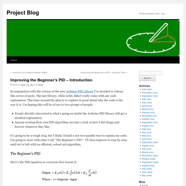
PID Theory Explained 1. Control System The basic idea behind a PID controller is to read a sensor, then compute the desired actuator output by calculating proportional, integral, and derivative responses and summing those three components to compute the output. Before we start to define the parameters of a PID controller, we shall see what a closed loop system is and some of the terminologies associated with it. Closed Loop System In a typical control system, the process variable is the system parameter that needs to be controlled, such as temperature (ºC), pressure (psi), or flow rate (liters/minute). In many cases, the actuator output is not the only signal that has an effect on the system. Figure 1: Block diagram of a typical closed loop system. Defintion of Terminlogies The control design process begins by defining the performance requirements. Figure 2: Response of a typical PID closed loop system. Some systems exhibit an undesirable behavior called deadtime. Back to Top 2. 3. Table 1. 4. [+] Enlarge Image

Related: