
Arduino Sensor Network. Previously, we looked at creating a Low Power Custom Arduino Sensor Board for use in a sensor network.
Now, let’s look at writing the software for our sensor network using that custom board. We will revisit the bathroom occupancy sensor as an example. Low Power Using Interrupts Last time we looked at optimizing power by sleeping the Arduino and waking it only when a door’s state changed. To do this, we used the pin change interrupt on pins 2 and 3. The Watchdog Timer (WDT) is a timer that runs on microcontrollers as a safety feature. We are going to use the WDT a little differently than its intended use. Let’s create a new Arduino project and setup the WDT. First, we create a flag variable that we use to know which interrupt was fired.
Next, we setup the WDT using some register bit manipulation. Revisiting the bathroom occupancy detector, the sensor board in charge of monitoring the downstairs bathrooms has to sense the input from 2 reed switches on the doors. A Library to Simplify. Udel_Skynet/Mirf_XMIT.ino at master · kelliott121/Udel_Skynet.
NRF24l01 - ElectroDragon. Features The Nordic Semiconductor nRF24L01 is descended from the TXRX24G, but it offers some important features that make it much easier to deal with: Enhanced Shockburst™: This is Nordic’s link layer protocol that gives the radio auto-acknowledgement, auto-retransmit, and packet loss detection capability.
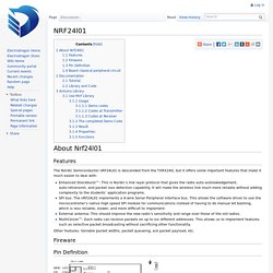
It will make the wireless link much more reliable without adding complexity to the students’ application programs. SPI bus: The nRF24L01 implements a 4-wire Serial Peripheral Interface bus. This allows the software driver to use the microcontroller’s native high speed SPI module for communications instead of having to do manual bit bashing, which is less reliable, slower, and more difficult to implement. Other features: Variable packet widths, packet queueing, ack packet payload, etc. Fireware Pin Definition Board and pin outs for NRF24L01B Board classical peripheral circuit Datasheet. nRF24L01-Mirf-Examples. Transmitting Strings with the nRF24L01. Hello!
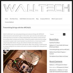
A while back I saw some people doing some awesome things with nRF24L01 radio transceivers and wanted to get in on the action. I got some tiny smd modules and tried to get them to transmit an analog reading between two arduinos, and found that the examples didn’t actually send any data! I looked for projects online, but the sending was buried in project code, it wasn’t posted, it was full of errors, or it just wasn’t worth using. Finally, Mike Rankin, the guy who builds the OLED watch displays, built a little nRF24L01 setup and shared the code with me. After some cleanup, I could transmit an analog reading from one arduino and read it on another and light LEDs along with the voltage level. The transmitter The receiver For a project I’m doing, I needed a link between an Arduino UNO and a YUN, the last of which is very picky about what you hook up to it, so serial, bluetooth, and everything else was out of the question.
Transmitting Arduino FileRADIOSEND Receiving Arduino File. Maniacbug/RF24. NRF24L01 Radio 2.4GHz Transmitter Receiver On Arduino. Charles W. | May 4, 2014 NRF24L01 is a 2.4GHz wireless radio frequency module that can be used to transmit and receive data.
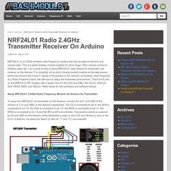
This is a great wireless module suitable for short range 100m remote control at 250kbps data rate. Let us look at how to setup NRF24L01 radio frequency transmitter and receiver on the Arduino. For simplicity, let us pick a simple joystick module as the data source where we transmit the X and Y values of the joystick to the receiver via wireless radio frequency at 2.4GHz frequency band. We will have to setup the transmitter and receiver. Setup NRF24L01 2.4GHz Radio Frequency Module On Arduino As Transmitter To setup the NRF24L01 as transmitter on the Arduino, connect the VCC and GND of the module to 3.3v and GND on the Arduino respectively.
Our intention is to have the A0 and A1 analog pins to collect the X and Y values of the joystick, and send the data wirelessly via NRF24L01 module. NRF24L01 Transmitter Sketch const uint64_t pipe = 0xE8E8F0F0E1LL; int joystick[2];