

This is a trace of the commands sent to and the responses received from an ESP8266 Wifi module as it connects to a website and receives a page of HTML. WiFiWebServer. Learning Examples | Foundations | Hacking | Links Examples > WiFi Library WiFi Web Server In this example, you will use your WiFi Shield and your Arduino to create a simple Web server.
Using the WiFi library, your device will be able to answer a HTTP request with your WiFI shield. After opening a browser and navigating to your WiFi shield's IP address, your Arduino will respond with just enough HTML for a browser to display the input values from all six analog pins. This example is written for a network using WPA encryption. Hardware Required. Montage Arduino / Wifi / LCD. Le montage électronique s'appuie sur le montage 11 (page 115) de l'"Arduino Project Book", le guide inclu dans le starter Kit.

Par contre, il faut faire évoluer les connexions entre le LCD et l'arduino pour éviter des incompatibilités entre le montage du LCD et les connexions du shield wifi. Le shield Wifi utilise les broches 4, 7, 10, 11 et 12 de l'arduino. Du coup, nous utilisons le montage ci-dessous : ESP8266 WiFi module. ESP8266 WiFi SoC has gained enormous popularity in the nick of time.
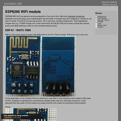
Right after hackaday introduction dedicated community forum was created despite that first batch of modules was still in shipping so virtually no one had it in hands. The key to success was its price - $5 or even less, including shipping fee. That's significantly cheaper than e.g. CC3000 module from Texas Instruments ($13.80 @ 1000 pcs for basic module that requires pretty much BGA soldering or $35 for more friendly breakout board). ESP-01 / Wi07C V090 ESP-01 is the most common variant, with PCB antenna and 2x4 100mils header. First Impression on the ESP8266 Serial-to-WiFi Module. Check my new blog post on the ESP8266 Toy Continuing from my previous blog post about Hi-Link HLK-RM04 module, I have finally received the ESP8266 Serial-to-WiFi module that I’ve been waiting for.

As I said previously, with the popularity of IoT devices, there is an increasing demand for low-cost and easy-to-use WiFi modules. ESP8266 is a new player in this field: it’s tiny (25mm x 15mm), with simple pin connections (standard 2×4 pin headers), and best of all, it’s extremely cheap, less than US$3 from Taobao.com! What is Serial-to-WiFi? Martyn Currey. Commands.png (PNG Image, 1008 × 586 pixels) Using the ESP8266 module. I obtained my module from an Ebay vendor in the United States.
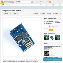
The shipping was faster than China, but more importantly, the vendor provides the module without the pins soldered in. The 8266 module isn't really breadboard friendly, but it's easy to convert it to a four pin module if you purchase the pin-less version. (or take a few minutes to remove the pins if you have obtained the other version) You'll need 5 pin connections to make the module work. (See image 1) RX, TX, ground, and 3v connected to two positions on the module. I sourced a 4pin female cable from my parts box and cut off one end. I used a small amount of nail polish to carefully paint over the unused pin, then looped the 3v connection from the power pin over the unused pin into the center. ESP8266 Wi-Fi Module with Teensy and Arduino – Kaspars Dambis.
Recently I ordered two Espressif ESP8266 breakout modules labeled “ESP8266 Version 01″ from hermann_shopp on ebay.
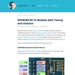
It is one of the coolest little chips for makers to have these days — it connects to the internet, has an open SDK with complete toolchain, multiple third-party firmware options such as Micro Python and NodeMcu (LUA). Even Hackaday loves it. Here is a quick overview of what I have learned so far. ESP8266 attached to an Arduino Leonardo. Getting Started with ESP8266 WiFi Transceiver (Review) This is a getting started guide for the ESP8266 WiFi Transceiver module.
Make sure you watch the video below. Watch the video below to see how it works! PetesTechProjects. Previously….

My previous post shows how I got life from my ESP8266 here: Once I got life and updated to latest firmware, I changed my baud rate to 9600 by giving “AT+CIOBAUD=9600″. Connecting to my Wifi AP Set my mode to “AT+CWMODE=3″ to allow for both client and server mode (at least that is what I think it is).Scan for access points with AT+CWLAP command.Join the AP by sending AT+CWJAP=”[YourNetwork]”,”[YourPassword]”I used an AP with WEP encryption and it worked for me.I used an AP with WPA encryption and it doesn’t work for me. Need to debug later.Check that you get IP assignment from the router with AT+CIFSRI got to IP’s, 192.168.4.1 and 192.168.0.128.The first one (192.168.4.1) is the IP of the AP that the ESP8266 when operating as an AP (remember I set to CWMODE=3 in step one). Here is a log capture of my TeraTerm window. OK AT+CWJAP=”PetesPrivateNetwork”,”xxxxxxxxxxx”) Setting up the ESP8266 as a server on Wifi network.
WiFi Serial Transceiver Module. In this tutorial, we'll use a seeeduino to control the ESP8266 WiFi module to request a static page from the internet.
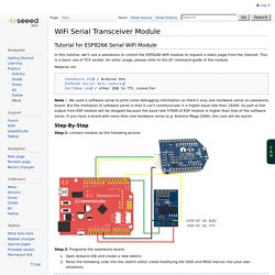
This is a basic use of TCP socket, for other usage, please refer to the AT command guide of the module. Material list: Seeeduino V3 / Arduino Uno ESP8266 Serial WiFi module UartSBee v4 / other USB to TTL converter Note: We used a software serial to print some debugging information as there’s only one hardware serial on seeeduino board. But the limitation of software serial is that it can’t communicate in a higher baud rate than 19200.
Step-By-Step Step 1: connect module as the following picture Step 2: Programe the seeeduino board. Open Arduino IDE and create a new sketch; Parse the following code into the sketch editor (need modifying the SSID and PASS macros into your own situation); Step 3: Open Serial Monitor and press the reset button of seeeduino board, you’ll see the output. At last, Happy Hakcing! ESP8266.