

RGB mood lamp. (3 sept. '06) Update: i made a new and better mood lamp.
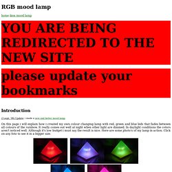
On this page i will explain how i created my own colour changing lamp with red, green and blue leds that fades between all colours of the rainbow. It really comes out well at night when other light are dimmed. In daylight conditions the colors aren't noticed well. Although it's low budget i must say the result is nice. Here are some photo's of my lamp in action. And because a video says 25 times more a second than a foto, here is a video: So if it's low budget, what did you use? I included a 4 port DIP switch which gives you the ability to: control the speed at which the colours change. choose the way colours change.
To give you an impression of how big the lamp is i placed it next to an ordinary shoe box. I made a small list of what you need to make your own colour changing lamp. For a the values of the components you can take a look at the circuit diagram below. On the foto below you can see the bottom of the lamp. GetLoFi – Circuit Bending Synth DIY. CtFLASHER. Handbook of hardware pinouts, cables schemes and connectors layouts @ pinouts.ru. EEPROM Programmer. EEPROM (E 2 PROM) is very easy to work with, since it just acts like a block of SRAM.

No special voltages, no mystical voodoo or anything. I designed this EEPROM programmer after I came to the conclusion that I was too broke to buy a real one, and that even if I wasn't too broke, they're a complete rip off. Most of them run $200 for something that can only be maybe an order of magnitude more complex than my $5 programmer. In my design, two 74x164s provide the address lines to the EEPROM, while one 74x299 universal shift register provides both read and write access to the data lines of the EEPROM. The parallel port is used to control all the 74-series components and the EEPROM. Before you get the schematics, please note that they are in the public domain, and are provided without warranty, and I disclaim all responsbility for everything that happens to anything. A PNG image and Xfig figure of the schematics are available. My C code isn't very pretty. USB Flash Cassette Mod - a photoset on Flickr.
Weak security in our daily lives. So, you know those cars with that keyless entry pad?
The one under the driver's side handle? Well, if you look closely you will see that there are really only 5 buttons, labeled "1/2", "3/4", "5/6", "7/8", "9/0". In an effort to avoid a little confusion, I'm going to call those buttons 1, 3, 5, 7, and 9, respectively. A little experimentation will reveal that, if the code is 11357, and you type 5113579, the door will still open! This means that with 7 characters we managed to try out 3 sequences - 51135, 11357, and 13579. Happy hacking! WebEE Tutorials. Circuit Simulator Applet. This java applet is an electronic circuit simulator.
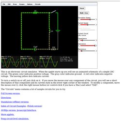
When the applet starts up you will see an animated schematic of a simple LRC circuit. The green color indicates positive voltage. The gray color indicates ground. A red color indicates negative voltage. The moving yellow dots indicate current. To turn a switch on or off, just click on it. The "Circuits" menu contains a lot of sample circuits for you to try. If you don't have Java, get the Java plug-in.
Directions. Index of Circuit Examples. More applets. Zip archive of this applet. SpokePOV: LED Bike Wheel Images. Spoke POV is an easy-to-make electronic kit toy that turns your bicycle wheel into a customized display!
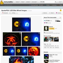
The project includes a free schematic design, open source software for uploading and editing stored bitmap images, and a high-quality kit with all the parts necessary to build your own. Tired: A red blinker on your seatpost Wired: Programmable full-wheel images in any color Specifications and Features: Can be used with road, mountain or BMX wheels! 30 LEDs on each side (22 for BMX) x 256 radial pixels Runs on 2-3 AA batteries for 10 hours or more, assuming 3000mAh alkalines and 50% image coverage. & check out more cool projects at. How to make PCB's with a laser printer.