
Harald Welte's blog. Arduino Optical Mouse ADNS-2051, ADNS-2610, ADNS-2083, PAN3101. In this tutorial I’ll describe how you can connect the optical sensor inside a cheap mouse to your Arduino and have it read out the x- and y-movements.

This will enable your Arduino to handle mouse input, detect surface movements, measure surface speed, etc. Materials This is what you need: Arduino board (any *duino will do) and the Arduino IDE.Optical mouse containing the PAN3101, ADNS-2610, ADNS-2083 or ADNS-2051 optical sensor. These sensors come in many mice sold today. Step 1 – Open up your mouse! The optical sensor and LED were covered with the black protective cap.
Step 2 –Take a look at the datasheets Check out the datasheet of the sensor you’re dealing with (Google).We only need to connect 4 pins of the sensor to the Arduino, of which two are used for data and two for the power supply. Step 3 – Cutting the controller wires (optional) To make sure the mouse’s own controller does not interfere with the Arduino, I had cut the SDIO and SCLK wires running to the chip in the mouse. The Lucas Eckels Blog » Larmie, the Arduino Alarm Scheduler. When I heard about Libelium’s Arduino Hacking Life contest, I knew it was time for me to finally solve one of my daily annoyances — setting the alarm clock.

Every night, the alarm gets set to a different time. Sometimes there’s an errand in the morning, sometimes an early meeting. On weekends, the alarm usually isn’t needed, unless something’s going on. And then in the morning, I need to set the clock again for my wife’s own set of daily scheduling variables. Enough! Larmie consists of four components: A regular alarm clock, with an interface cable addedAn Arduino with a custom shield, for interfacing with the clockA computer, which regularly updates the Arduino with what time to set the alarm toA calendar system. To start, I cracked open my 10+ year old alarm clock.
What I want to do is twiddle the voltage on the LM8560′s input pins, to simulate pressing the buttons on the clock. The Arduino expects to be told the alarm over a serial connection. Source code for Larmie. Basics: Finding pin 1. You’ve got your components, and your datasheet, and you’re read to start hacking.
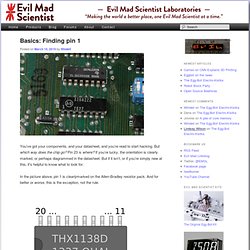
But which way does the chip go? Pin 23 is where? If you’re lucky, the orientation is clearly marked, or perhaps diagrammed in the datasheet. But if it isn’t, or if you’re simply new at this, it’s helpful to know what to look for. In the picture above, pin 1 is clearlymarked on the Allen-Bradley resistor pack. Here is a basic rule that applies for mostintegrated circuits: There’s a polarity mark somewhere.
A common polarity marker is a half-moon shape at one end of the chip. Often pin 1 is in a corner of the chip, and it’s only that corner– not the pin itself –that is marked by the small circle or triangle. In this sketch, we’ve drawn an imaginary part number “THX1138D,” manufactured in week 37 of 2013, and it has a mysterious lot or internal code “OHAI” that may or may not be explained in the datasheet. As we’ll see, there are plenty of examples of this, or close variations on it.