
Cats-fs.rpi.edu/~wenj/ECSE641S07/delta_calibration.pdf. Arm length and home angle. Delta robot. The FANUC M-1iA Delta Robot, released in 2009.
Sketchy, a portrait-drawing delta robot[1] A delta robot is a type of parallel robot.[2] It consists of three arms connected to universal joints at the base. The key design feature is the use of parallelograms in the arms, which maintains the orientation of the end effector. By contrast, a Stewart platform can change the orientation of its end effector.[3] Delta robots have popular usage in picking and packaging in factories because they can be quite fast, some executing up to 300 picks per minute.[4] History[edit] The delta robot (a parallel arm robot) was invented in the early 1980s by a research team led by professor Reymond Clavel at the École Polytechnique Fédérale de Lausanne (EPFL, Switzerland).[5] The purpose of this new type of robot was to manipulate light and small objects at a very high speed, an industrial need at that time.
Design[edit] The robot's base is mounted above the workspace and all the actuators are located on it. Delta robot kinematics - Tutorials. The delta robot consists of two platforms: the upper one (1) with three motors (3) mounted on it, and smaller one (8) with an end effector (9).
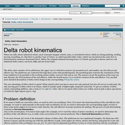
The platforms are connected through three arms with parallelograms, the parallelograms restrain the orientation of the lower platform to be parallel to the working surface (table, conveyor belt and so on). The motors (3) set the position of the arms (4) and, thereby, the XYZ-position of the end effector, while the fourth motor (11) is used for rotation of the end effector. You can find more detailed description of delta robot design in the corresponding Wikipedia article. Tiny gadgets. With a simple cartesian robot (or printer), the mechanism moves directly along rails in each of the x, y and z directions.
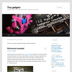
If you want to move a print head from the origin to, say, (10,10,20) you simply direct the motors to move it 10mm along the x axis rail, 10 along the y axis rail and 20 along the z. You get the idea. With a delta configuration, it’s not so simple. Moving any one of the carriages which run up and down the three vertical struts will cause movement of the tool head in x,y and z simultaneously. Calculations are required to work out how to move all three carriages at the same time to move the print head to the right place. Suppose we want to move the extruder nozzle to a particular point. A2 = (a2x,a2y,a2z), B2 = (b2x,b2y,b2z) and C2 = (c2x,c2y,c2z). The diagram below shows this a bit more clearly: A1 = (a1x,a1y,a1z), B1 = (b1x,b1y,b1z) and C1 = (c1x,c1y,c1z). The diagram below shows how we can calculate these.
a2z = tz + to + hab2z = tz + to + hbc2z = tz + to + hc. Kossel frame calculator. 3D printing with a delta robot that seems to simplify the concept. This 3d printing delta robot really seems to solve a lot of the hurdles faced by previous offerings.
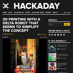
With other delta printers we’ve looked at the motor control of the three arms is usually a it complicated. On this build the motors can just be seen in this image at each corner under the build platform. Each motor has a belt that loops from the bottom to the top for the machine, driving an arm along two precision rods. It’s also interesting to note that the printer head doesn’t have a motor mounted on it for feeding the filament.
Instead, the motor is mounted remotely. RepRapCalculator. Graphical solutions of working space for my "Rostock" Calculus - "Cut" (hexagon-like) Reuleaux triangle area. Rostock_Print_Area.png (PNG Image, 741×670 pixels)