
A Sensitive DIY Ultrasonic Range Sensor. I needed some ultrasonic range finders for my project.
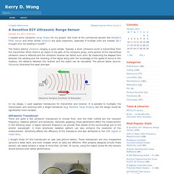
But most of the commercial sensors like Parallax’s PING sensor and other similar products are quite expensive, especially if multiple units are needed. So I thought why not building it myself? The theory behind ultrasonic ranging is quite simple. Typically a short ultrasonic burst is transmitted from the transmitter. When there is an object in the path of the ultrasonic pulse, some portion of the transmitted ultrasonic wave is reflected and the ultrasonic receiver can detect such echo. Ultrasonic Ranging (Courtesy of Wikipedia) In my design, I used separate transducers for transmitter and receiver. Ultrasonic Transducer There are quite a few ultrasonic transducers to choose from, and the main criteria are the resonant frequency, radiation pattern and sensitivity.
I bought these 24 kHz transducers on sale (see picture below). 24 kHz Ultrasonic Transducers. Project – Simple RFID access system - Birds on the Wire. Hello Readers The purpose of this project is to prototype a basic RFID access system. Although it is not that complicated, this article is my response to a kit reviewed in the Australian “Silicon Chip” (November 2010) electronics magazine. Their article describes the kit in detail – operation, schematic, use and installation. However the code for the microcontroller (PIC16F628A) is not published due to the kit manufacturer holding copyright over the design. This is a shame, as many organisations have been quite successful selling open-source kits.
Original article There are pros and cons with the original vs. my version. The feature requirements are few. This is a simple thing to make, and the transition from a solderless breadboard to strip board will be easy for those who decide to make a permanent example. When selecting a relay, make sure it can handle the required load current and voltage - and that the coil current is less than 100mA . And here is the schematic: Arduino I2C Sniffer » johngineer. I’m working on an I2C project, but I don’t have a sampling oscilloscope and I need to see what the heck is going on, so I put together this quick and dirty I2C sniffer sketch.
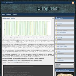
You connect two digital pins on the Arduino to the I2C bus lines SDA and SCL, and Arduino ground to I2C ground. The digital pins on the Arduino must be on PORTD, which are pins 0 through 7. It’s probably a good idea to avoid the serial lines, which means you should use any two pins between 2 and 7. It captures the data (within a certain time window) and then it sends CSV-formatted output to the serial port. You can then take this data and plot it to get an idea of what’s going on on your I2C bus. This code runs a “one-shot” capture, meaning that it only captures data once and then dumps it to the serial port.
You can adjust the capture window to suit your needs, though bear in mind that the ATMega328 only has 2k of RAM, so values approaching 2000 may not work so well. The code is CC-BY-SA 3.0 and unsupported. The Imaginary Marching Band.