

AC2_OptFlow - arducopter - Arduino-based autopilot for mulitrotor craft, from quadcopters to traditional helis. Optical Flow Sensor To improve position hold accuracy ArduCopter now supports the sold by the DIY Drones store.
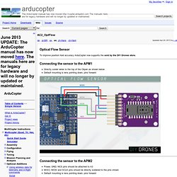
Connecting the sensor to the APM1 Directly solder wires to the top of the Oilpan as shown below Default mounting is lens pointing down, pins forward Connecting the sensor to the APM2 Power, GND, NCS pins should be attached to A3 MISO, MOSI and SCLK pins should be directly soldered to the pins shown Default mounting is lens pointing down, pins forward Connecting the sensor to the APM2.5 Connect VCC, GND, MISO, MOSI, SCLK and NCS pins as shown in the diagram below (it's a standard [ ICSP header) Default mounting is lens pointing down, pins forward Cut and resolder the MISOLVL jumper on the back of the board to switch the MISO pin to work on 3.3v. Testing the sensor Open the AP_OpticalFlow_test.pde sketch in the arduino IDE if you are using an APM2 modify lines 22 and 23 to look like below: Capturing an image from the sensor How it works We compensate for vehicle roll and pitch changes.
Safety & Perfomance Through Innovation. GPS Receiver (MTK3339) Looking to add location awareness to your next project this is the perfect solution.
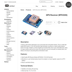
This is a really high quality GPS receiver (10 Hz, 66 Channels & high sensitivity) mounted on a really friendly breakout board (3-5v logic compliant, on board regulator & mounting holes) all for a very reasonable price. Using it is super simple as well, just four wires, then either get it up and running with an example sketch (link below) or the easy to use parsing library (link below) to start. Regional aeromagnetic anomalies in Ellsworth Land: Crustal structure and Mesozoic microplate boundaries within West Antarctica - Maslanyj - 2012 - Tectonics. Options for accessing this content: Type your institution's name in the box below.

If your institution is a Wiley customer, it will appear in the list of suggested institutions and you will be able to log in to access content. Some users may also log in directly via OpenAthens. Please note that there are currently a number of duplicate entries in the list of institutions. We are actively working on fixing this issue and apologize for any inconvenience caused. Registered Users please login: Access your saved publications, articles and searchesManage your email alerts, orders and subscriptionsChange your contact information, including your password Please register to: Save publications, articles and searchesGet email alertsGet all the benefits mentioned below!
Register now > ArduIMU+ V3. Important Note: ArduIMU is not an Autopilot.
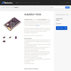
It's just an orientation solution (the heart of an Autopilot) and can be used on anything where you want to know its orientation in respect to the ground--boats, cars, rockets or even your dog. To learn more about IMUs read here. ArduIMU V3 features the new MPU-6000 that includes 3 axis gyros & accells built-in, the latest 3 axis I2C magnetometer HMC-5883L and the classic but very robust Arduino Atmega328 running at 16Mhz... MPU-6000 uses SPI for max performance.
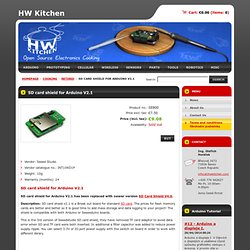
Specifications: Other ArduIMU V3 features: Pin compatible with ArduIMU V2.Breadboard compatible (ArduIMU V2 was not!). SD card shield for Arduino V2.1. #12 - Arduino a displeje I.
Arduino a displeje I. V článcích o displejích si ukážeme různé způsoby grafického výstupu z Arduina. V prvním díle si předvedeme, jak používat maticové LED displeje. Také se zaměříme na platformu Rainbowduino a ukážeme si i pár příkladů využití. Úvod U velké části projektů se dostaneme do situace,... #11 - Propojujeme Arduino s jinými zařízeními. MicroSD Shield Quickstart Guide. MicroSD Shield Quickstart Guide Skill Level: Beginner by zagGrad | May 18, 2010 | 26 comments microSD Shield From digital cameras to smart phones and even some laptops, SD cards are found everywhere.
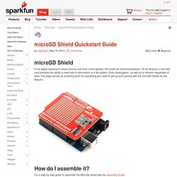
On an Arduino a microSD card provides the ability to save lots of information to a file system (think dataloggers), as well as to retrieve megabytes of data. How do I assemble it? CRC Implementation Code in C. By Michael Barr CRCs are among the best checksums available to detect and/or correct errors in communications transmissions.
Unfortunately, the modulo-2 arithmetic used to compute CRCs doesn't map easily into software. This article shows how to implement an efficient CRC in C. I'm going to complete my discussion of checksums by showing you how to implement CRCs in software. I'll start with a naive implementation and gradually improve the efficiency of the code as I go along. For most software engineers, the overwhelmingly confusing thing about CRCs is their implementation. Modulo-2 binary division Before writing even one line of code, let's first examine the mechanics of modulo-2 binary division. Figure 1. The modulo-2 division process is defined as follows: The final value of the remainder is the CRC of the given message. What's most important to notice at this point is that we never use any of the information in the quotient, either during or after computing the CRC. Bit by bit Listing 1.
Tutorial: Arduino and XBee Communication. --D.
Thiebaut 17:47, 9 April 2012 (EDT) Setup The setup is simple: Windows PC <---USB-cable---> Xbee (receiver) <--wireless--> XBee (Xmitter) <---> Arduino Instead of a pure Windows machine, we're using a MacPro running Windows in Parallels.