
Anfängerproblem mit stl-Datei (Produktvisualisierung - Industriedesign/Rhino3D) - Foren auf CAD.de. STL-Schnittstelle. Vorlage:Infobox Dateiformat/Wartung/MagischeZahl fehltVorlage:Infobox Dateiformat/Wartung/Standard fehltVorlage:Infobox Dateiformat/Wartung/Website fehlt Bei der STL-Schnittstelle (Surface Tesselation Language; deutsch etwa Sprache zur Beschreibung der Oberfläche durch Dreiecke oder Standard Triangulation Language und mit unbekannter Herkunft auch Standard Tesselation Language) handelt es sich um eine (Quasi-)Standardschnittstelle vieler CAD-Systeme.
Dieses Dateninterface dient hauptsächlich der Bereitstellung geometrischer Informationen aus dreidimensionalen Datenmodellen heraus für die Fertigung mittels generativer Fertigungsverfahren oder Rapid Prototyping-Anlagen. Die Bezeichnung Stereolithografie-Schnittstelle hat ihre Begründung in der Tatsache, dass Stereolithografie-Anlagen (SLA) die ersten kommerziell verfügbaren Anlagen waren, die eben mit dieser Geometriebeschreibung betrieben wurden. Definition[Bearbeiten] Gekrümmte Oberflächen werden durch die Dreiecke nur angenähert. Fabbers.com > The StL Format: Standard Data Format for Fabbers Reprinted from Section 6.5 ofAutomated Fabrication by Marshall Burns, Ph.D.Used with permission. Technical source:StereoLithography Interface Specification, 3D Systems, Inc., October 1989.
An StL file consists of a list of facet data.
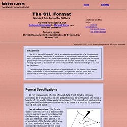
Each facet is uniquely identified by a unit normal (a line perpendicular to the triangle and with a length of 1.0) and by three vertices (corners). The normal and each vertex are specified by three coordinates each, so there is a total of 12 numbers stored for each facet. Facet orientation. The facets define the surface of a 3-dimensional object. As such, each facet is part of the boundary between the interior and the exterior of the object. Vertex-to-vertex rule. The object represented must be located in the all-positive octant. The official 3D Systems StL specification document states that there is a provision for inclusion of “special attributes for building parameters,” but does not give the format for including such attributes.
Sorting the triangles in ascending z-value order is recommended, but not required, in order to optimize performance of the slice program. The StL standard includes two data formats, ASCII and binary. Rapid Prototyping, Polyjet and Stererolithography Services. How to convert .stl files. How to create Stereolithography .stl files The Rapid Prototyping Process uses .stl or Stereolithography files to build physical 3D Cad Models.
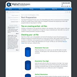
Stl files are created using a mesh made from triangles to represent the physical part. Most CAD programs allow an easy export of .stl files. Tips on creating perfect .stl files Faceting, or flat spots on your part file are relative to the resolution of the .stl file. Checking your .stl file Open the .stl file in your cad application and look at the faceting to ensure the part appears as designed checking for excessive flat spots on curves and contours. Instructions for .stl Creation Here are instructions to create .stl files from Popular CAD applications. Alibre FileExportSave As > STLEnter File NameSave Ashlar-Vellum File > Export…Select STL Export TypeSet Export Options to Binary > OKEnter FilenameSave AutoCAD Your design must be a three-dimensional solid object to output an STL file.
Autodesk Inventor CADKey IronCAD Mechanical Desktop ProE ProE Wildfire Rhino.