
Embedded Linux, kernel and real-time presentations. Free training materials and conference presentations from Free Electrons, covering kernel, real-time, Android, embedded Linux system and device driver development.
License All our documents are available under the terms of the Creative Commons Attribution-ShareAlike 3.0 license. This essentially means that you are free to download, distribute and even modify them, provided you mention us as the original authors and that you share these documents under the same conditions. Complete training materials Presentations at technical conferences Here are the most recent versions of presentations we made at technical conferences.
Linux kernel An overview of the DMAEngine subsystem (ELC, Mar. 2015) Understanding the DMAEngine subsystem in the Linux kernelDevice Tree as a stable ABI: a fairy tale? Embedded Linux Android Introduction to Android and system bring-up (Captronic events, 2012) Legacy documents These documents are not actively maintained any more. Kernel Architecture specific documents. - StumbleUpon. Digital Oscilloscope ECE 4760 Final Project Emily McAdams, egm23 Luke Diamente, lad97 Richard Wu, rsw35 Introduction. 2 High Level Design. 3 Background Math. 3 Logical Structure. 4 Patent, Copyright and Trademark Concerns. 4 Hardware Design. 5 Level Shifter and Amplifier. 5 Microcontroller Boards and Microcontrollers. 5 Digital to Analog Converter. 6 Analog to Digital Converter. 7. Convolutions. Convolutions are a really cool way to smooth and even differentiate data.
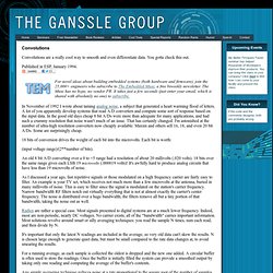
You gotta check this out. Published in ESP, January 1994. In November of 1992 I wrote about taming analog noise, a subject that generated a heart warming flood of letters. A lot of you apparently develop systems that read A/D converters and compute some sort of response based on the input data. In the good old days cheap 8 bit A/Ds were more than adequate for many applications, and had such a crummy resolution that noise wasn't much of an issue. 18 bits of conversion drives the weight of each bit into the microvolts. (input voltage range)/(2**number of bits). An old 8 bit A/D converting over a 0 to +5 range had a resolution of about 20 millivolts (.020 volts). 18 bits over the same range gives each LSB 19 microvolts (.000019 volts)!
As I discussed a year ago, fast repetitive signals or those modulated on a high frequency carrier are fairly easy to filter. Radios are rather a special case. Inspiring Creations. PROJECTS. Microcontrollers as Material We’ve developed a set of tools and techniques that make it easy to use microcontrollers as an art or craft material, embedding them directly into drawings or other artifacts.
We use the ATtiny45 from Atmel, a small and cheap (~$1) microcontroller that can be glued directly to paper or other objects. We then construct circuits [...] Codeable Objects Codeable Objects is a library for Processing that enables novice coders, designers and artists to rapidly design, customize and construct an artifact using geometric computation using geometric computation and digital fabrication The programming methods provided by the library allow the user to program a variety of structures and designs with simple code and geometry.
TRANSISTOR THEORY. Figure 2-4.—Transistor constructions. Build an analog vocoder. The first thing we need is a circuit design, which I am posting as a series of images. I designed it from scratch, although I did investigate as many vocoder schematics I could get my hands on. I focused on using easily obtainable components that are inexpensive, and I tried to keep the circuit as simple as possible without sacrificing functionality. A vocoder basically has two inputs and one output. The first input is the program (usually a connected to a microphone) and the second input receives a carrier signal (usually a keyboard). The program signal is then fed to an analysis section, which extracts the spectral information from the sound and applies it to the carrier signal.
First, we must have input amplifiers for each of the two inputs. Each channel in the analysis section consists of two identical band pass filters. Your First Robot Volume 2. Neets Module 07-Introduction to Solid-State Devices and Power Supplies. Design & Technology On The Web - Electronics help for students - Integrated Circuits - 555 timer IC and the way to calculate the time dealys that will make the component useful - Attractive easy to follow guide for KS3 and GCSE - Monostable 555 timer circ. Using the 555 Timer, 741 OP Amp and … others The 555 timer has eight pins – It is a DIL package (Dual In-Line) - It as two rows of four pins in-line !
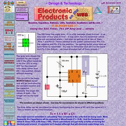
It may seem hard to remember which pins are connected where – but start by getting rid of two of them. Pins 1 and Pin 8 – These connect to the power connections: Pin 1 to the negative and Pin 8 to the positive. Its getting better since now we have fewer to remember. Try now to remember that pin 2 is the Input and Pin 3 the Output - we have allocated half of them already ! The grey area shows the position for the output LED if the effect required is for the LED to stay OFF for the required time delay rather than ON – the position shown without shading. . * Pin numbers are always shown – but may for convenience be shown in different positions. The time delay can be calculated by simply multiplying the value of R1 with the value of C1.
Tc = 1.1 x R1 x C1. Make: Projects How-to Projects Library - Electronics, Arduino, Crafts, Solar, Robots.