
555 and 556 Timer Circuits. Understanding Schematics. You can see that there are various bits represented by symbols, all connected in various ways.
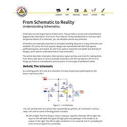
Let’s look at some of the big picture concepts: Left to Right: The first thing to notice is that you read the schematic left-to-right: the input on the left feeds the signal through parts and pathways in the middle to an output on the right. This left-to-right convention is not universal, but it is probably the most common layout for a schematic. Parts list - msarnoff.org ChipDB. Help me wire an illuminated rocker switch. DIY Electronics.