
Arduino BitBang. Sources Tuto qu'on a suivi Pourquoi ?
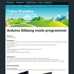
Si vous achetez un atmel, qui ne coute qu'environ 3€, vous pouvez le programmer aussi bien qu'un arduino, et c'est plus facile a integrer dans un montage Seul problème: le programmeur coute une fortune, pas besoin de depenser d'argent si vous avez déja un arduino! Materiel Necessaire: Arduino 1 Atmel, peu importe lequel (atmega8, atmega 16, atmega 32 ou atmega 168) Des "pins" secables (4) Quelques cables et si possibles une plaquette d'essai Comment ? On va utiliser la puce qui se trouve sur l'arduino pour communiquer en usb entre le pc et l'atmel. Partie Materielle Pins sur l'arduino Il faut souder les 4 pins secables sur l'arduino, attention de ne pas faire cramer la puce! Branchement de l'atmel on va recuperer l'alimentation du port icsp de l'arduino, et le reste des 4 pins que l'on vient de souder.
On a maintenant une prise icsp qui peut programmer n'importe quel atmel! Du côté de l'atmel, justement nous avons deux choix qui s'offre a nous: Conclusion. RotaryEncoders. ALPS STEC12E07 Encoder A rotary or "shaft" encoder is an angular measuring device.
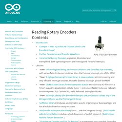
It is used to precisely measure rotation of motors or to create wheel controllers (knobs) that can turn infinitely (with no end stop like a potentiometer has). Some of them are also equipped with a pushbutton when you press on the axis (like the ones used for navigation on many music controllers). They come in all kinds of resolutions, from maybe 16 to at least 1024 steps per revolution, and cost from 2 to maybe 200 EUR. I've written a little sketch to read a rotary controller and send its readout via RS232. It simply updates a counter (encoder0Pos) every time the encoder turns by one step, and sends it via serial to the PC.
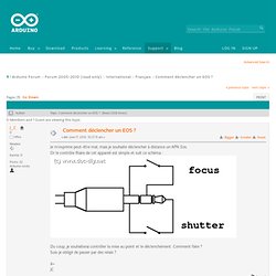
This works fine with an ALPS STEC12E08 encoder which has 24 steps per turn. I learned about how to read the encoder from the file encoder.h included in the Arduino distribution as part of the AVRLib. Example 1 Oh, a few notes: Interrupt Example Below is some code that uses an interrupt. Time-Lapse Astronomy. Comment déclencher un EOS ? Après quelques recherches et quelques essais sur mon Canon EOS 500D, je suis arrivé à ça : Schéma en haut, pour Canon EOS, ou bien (avec la prise qui va bien) pour Sony alpha.Schéma du bas pour Panasonic GF1 et autres ayant la prise de télécommande.
#define MAP_PIN 3 #define CLIC_PIN 2 int tempo_map = 400; // durée laissée à la mise au point, ici 400 ms à réglerint tempo_clic = 200; // durée pour le contact du shoot, ici 200ms à régler void setup() { // initialisation des pin digitaux de l'arduino pinMode(MAP_PIN, OUTPUT); pinMode(CLIC_PIN, OUTPUT); } void loop() // Code test pour un déclenchement avec mise au point toutes les 5 secondes{ digitalWrite(MAP_PIN, HIGH); delay(tempo_map); digitalWrite(CLIC_PIN, HIGH); delay(tempo_clic); digitalWrite(MAP_PIN, LOW); digitalWrite(CLIC_PIN, LOW); delay(5000); } J'ai pris un optocoupleur équivalent au PC827 car c'est un double canal.
PS : je ne suis pas doué en schéma électronique, si vous avez mieux, je suis preneur. Tutorial: manage menu and LCD display with Arduino. Working on my MIDI ribbon controller I needed to implement a menu to easily configure several parameters, but I found information on how to handle a menu, how to manage an LCD display, but very poor info on how to combine the two things.
However, thanks to Alexander Brevig Menubackend library I managed to create the menu I wanted.I downloaded the Alexander Brevig Library version 1.4 and I slightly modified it adding, at line 195 of the MenuBackend.h file , immediately before the line "private:", this method: void toRoot() { Intervallometre. How to make and use the arduino as an Isp for an ATtiny 45/85. Ressources pour l'interactivité. Arduino est distribué avec la logithèque Wire qui permet une communication I2C et Two Wire.
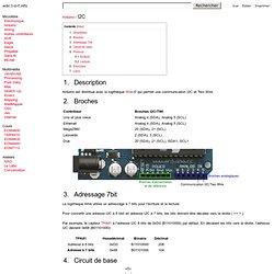
La logithèque Wire utilise un adressage à 7 bits pour l'écriture et la lecture. Pour convertir une adresse I2C à 8 bist en adresse I2C à 7 bits, les bits doivent être décalés vers la droite ( >> 1 ). Par exemple, le capteur TPA81 à l'adresse I2C 8 bits de 0xD0 (B11010000) par défaut. En décalant les bits vers la droite, l'adresse I2C devient 0x68 (B01101000): Rp=1.8k 5.1 Écriture // Set register and write data Wire.beginTransmission(ADDRESS); Wire.send(REGISTRE); Wire.send(DATA); [...] 5.2 Lecture.